1/350 Scale Star Trek Original Series
Enterprise
This build is a custom
build for my wife, as she digs the Trek. Unlike every other build this decade,
I believe I will get this one done relatively soon as I have her blessing, and despite
its size it is a relatively straightforward kit (think the old AMT/ERTL kit on
MASSIVE ROIDS!!!!). I was able to get
her to settle on the production version, though I may keep the 2nd pilot parts
handy for quick swapping. That would really boil down to the bridge dome, the
nacelle rear caps, the goofy big deflector and Bussard scoops. 99.9% of
humanity wouldn't know about the neck light pattern or the decal differences...
I'm building this kit lit with the following parts/objectives:
1. Production build.
2. PL light kit and photo etch.
3. Blue nacelle lights.
4. Lit Galileo shuttle in bay.
5. Paragraphix PE set.
6. Custom metallic paint scheme
Since there are a number of builds across YouTube and modeling forums going on,
I'm limiting my posts to areas or things I'm doing (or think I'm doing!)
different or that may be useful to others. Obviously the YouTube videos out
there are highly recommended.
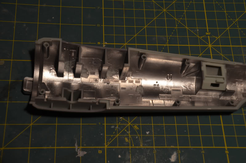
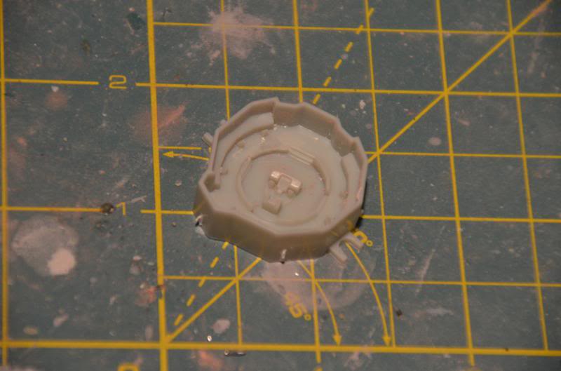
So, first shot is of the never to be seen again production date stamp. Kind of
cool to see this:

As a lighted kit, the first order of business is to light block as much as
possible. For this, I did masking tape on the glue joints and used Krylon
sandable primer, blowing through about a can to do all the parts. Exterior
priming was easier--all I did was put the parts together, letting the natural
seams once joined protect themselves from Duplicolor primer. I used Krylon on
the inside and Duplicolor on the exterior primarily because I didn't have
enough Duplicolor for both, and I figured the darker Krylon would work better
for light blocking and for the next coat. For the interior chrome paint I used
a $3.99 can of Rustoleum metallic chrome. Normally I'm not a fan of Rustoleum,
but this particular chrome I like--it dries fairly hard, fairly fast. For the
amount of paint I dumped on this kit, it should have been a gummy mess. More
importantly, it works very well as a light block.

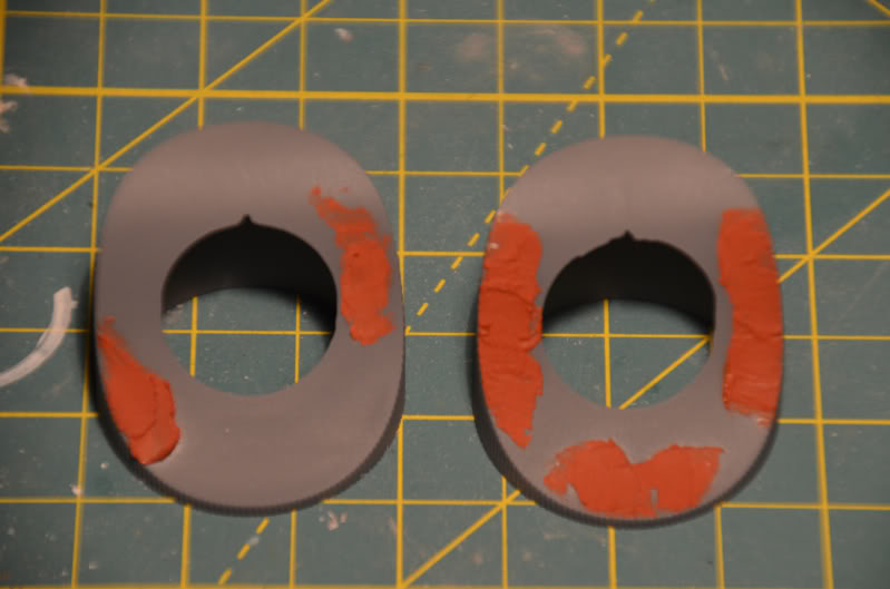
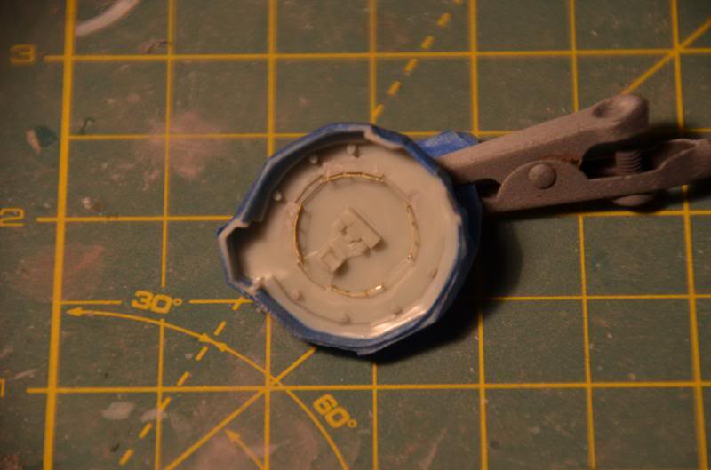
Most of the masking was fairly easy, except the upper saucer interior. This is
the one part that doesn't have any framework or interior structure to guide the
masking. So, using liquid mask, I applied the liquid mask to all the joint
surfaces on the lower saucer section, and put the two parts together. The wet
mask was transferred to the upper section, giving me pretty much exactly where
I didn't want paint to go. Another advantage of the wet mask is since I was a
little sloppy with the tape, it gave me a chance to fix the areas I needed to
on the lower saucer:


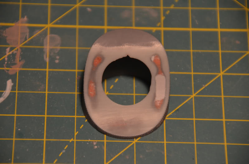
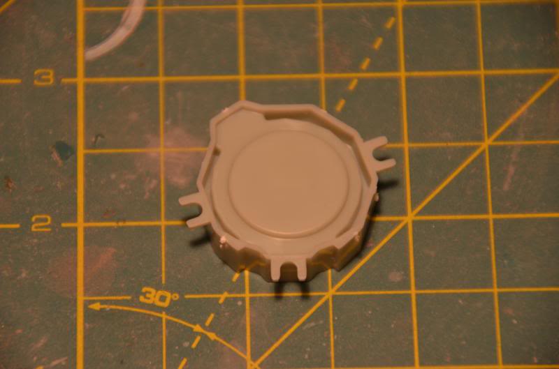
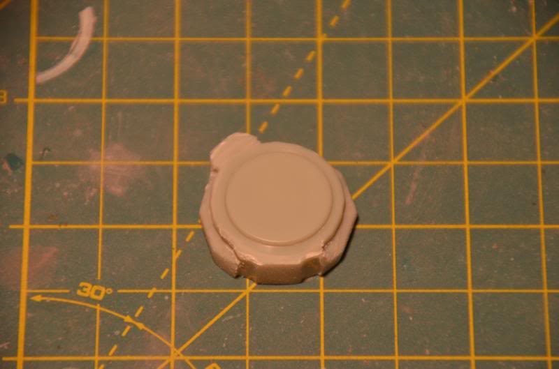
The results, before priming and after chroming, are below.


An added benefit I
discovered much later is with the lighting kit.
When you are routing the wiring and lights for the upper saucer, having
the lower saucer connection points clearly defined is a huge help in making
sure none of the wires will get pinched or interfere with construction. Without that masked “map”, especially around
the neck area, the wiring would get dicey.

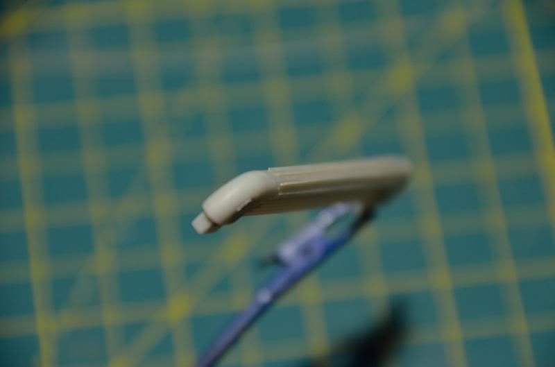
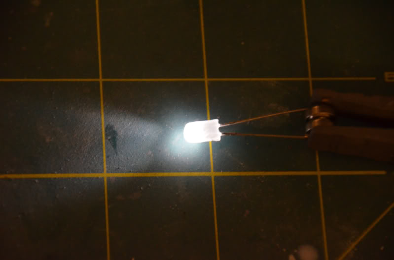
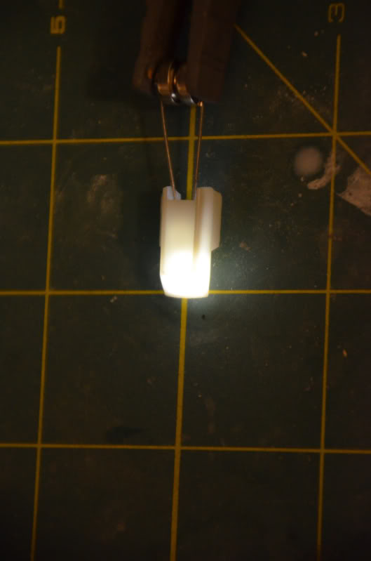
One other trick I used concerns the Bussard lights, or "Christmas" bulbs.
On other models where I have needed to frost a clear part, a simple trick is to
dip it in acetone. The technique is fairly simple (I trashed a few green bulbs
working out the best method). Basically, grasp the part by the stem with
tweezers, and dip for a 5 count into the acetone. After pulling it out, gently
blow on the underside of the bulb until dry, a few seconds at most. Then, set
aside to fully dry. You can see the results below.
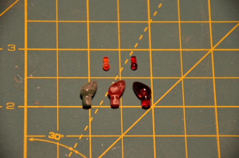
Another nifty time saving tip--don't bother sanding the seams off the Christmas
bulbs. Once you frost the inner spinner dome and the outer Bussard scoop with steel
wool, there is no way in the Federation or the Empire those seams are visible.
I of course started the light tests with the Bussard scoops, which was truly
cool as crap to see running (even after seeing a dozen YouTube videos of the
same!) Unfortunately, one of my boards is dead--the random 5 blinking small
bulbs didn't work, so that was sent back to PL for replacement.
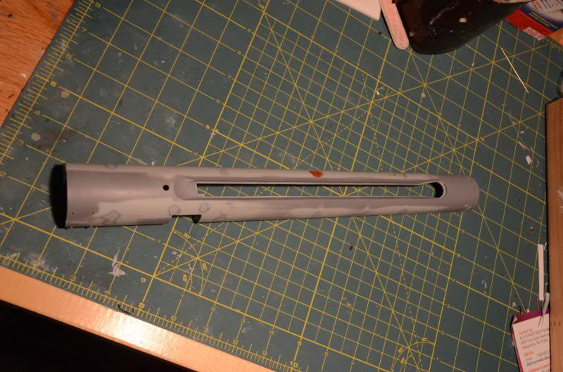
I also wanted to get started on the Warp pylons, as I want the glue to be set
set SET when I put this bad boy together. I've never been a huge fan of endless
masking little windows, which is part of the reason this is my favorite Trek
kit. That said, I decided to try something new (to me). I took the window
sections and carefully applied liquid mask.

At the same time, I primed the exteriors of the pylons and sanded them with 600
grit paper. I carefully inserted the window blanks, which don't quite fit
without bowing, glued them in place, and then glued the crap out of the pylons.
Note the instructions refer only to edge gluing, but you can and should also
glue the truss structure too.

Now I have perfectly masked windows, which in theory will survive the color
coats, gloss coats until they come off for the final flat coats. In theory.
It's not as dangerous as cold starting the engines with a controlled implosion,
but if it doesn't work I'll be certainly disappointed. Ultimately, I'll need to
get color coats on the pylons before I get too far down the road with the neck
or hulls and realize it doesn't work.
On a truly happy note,
BTW, I have my replacement board from PL. I had a bad one with no blinky, and
it took them all of a week to replace it. Also got a replacement Bussard
dome--now I can use my chipped one for masking during painting.
Important tip when removing all the sprue attachments on the Bussard: when
clipping, make sure the tip of the nippers extends a few millimeters beyond the
attachment point. If you try to "nibble" the piece off, you might end
up having it chip like mine did. By having the attachment point completely
within the blades of the nippers, you'll get a clean cut every time.
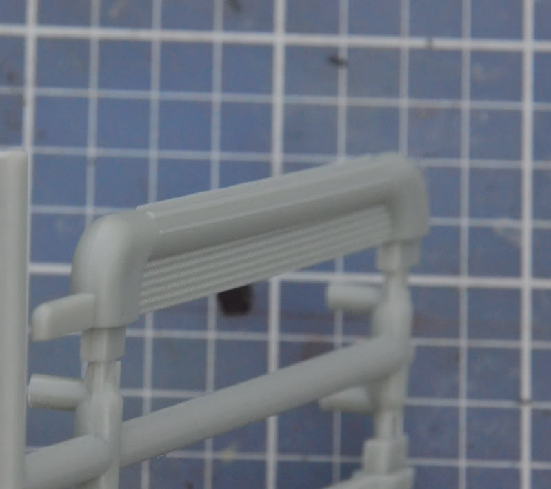
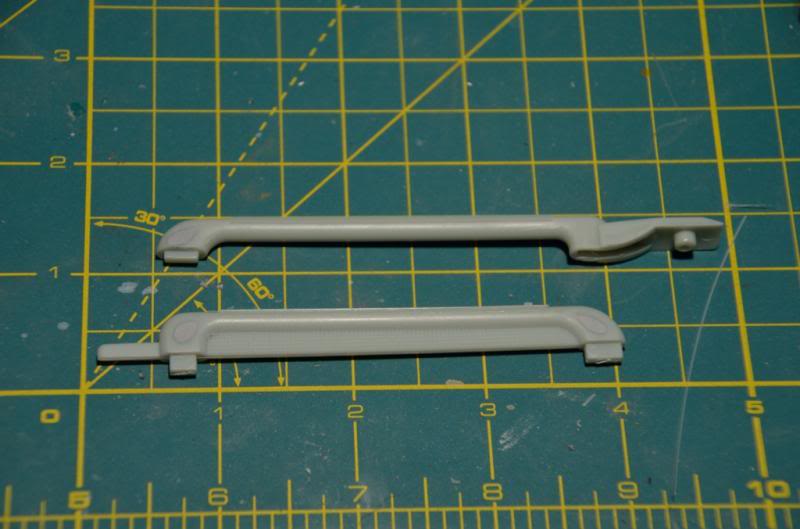
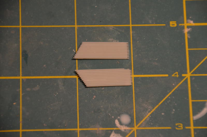
Did a little more today
before being wiped out by a stomach flu. Working on the nacelle struts, there
are two options. You can go with the molded in detail, or flip the parts around
to the smooth side and use photoetch. I went with the PE option for my lovely
customer. Below you see the molded in detail, which is actually pretty damn
good, and I'm sure would look great with a black wash over the gray paint.
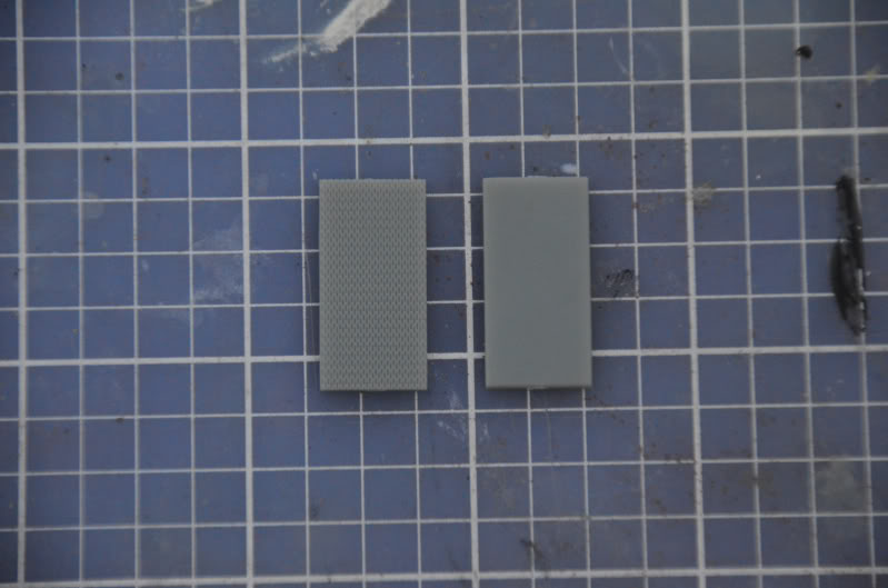
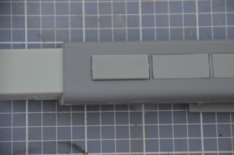
Note these panels are mildly trapezoidal edge on, so to get them to fit you
have to file/sand all four edges.
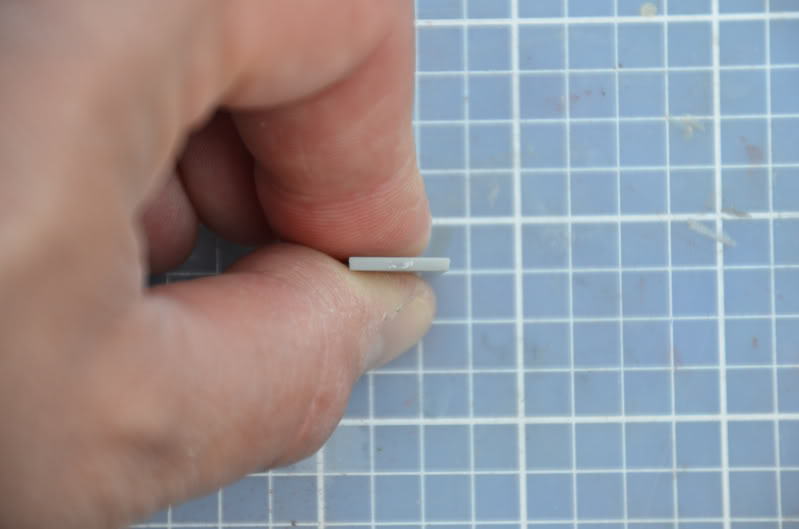
Without sanding or filing
down the long edges, you end up with a hideous fit (one of these things is not
like the other):
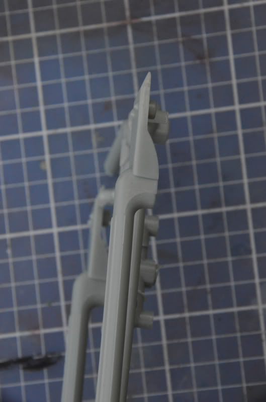
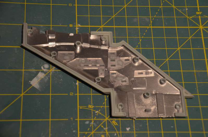
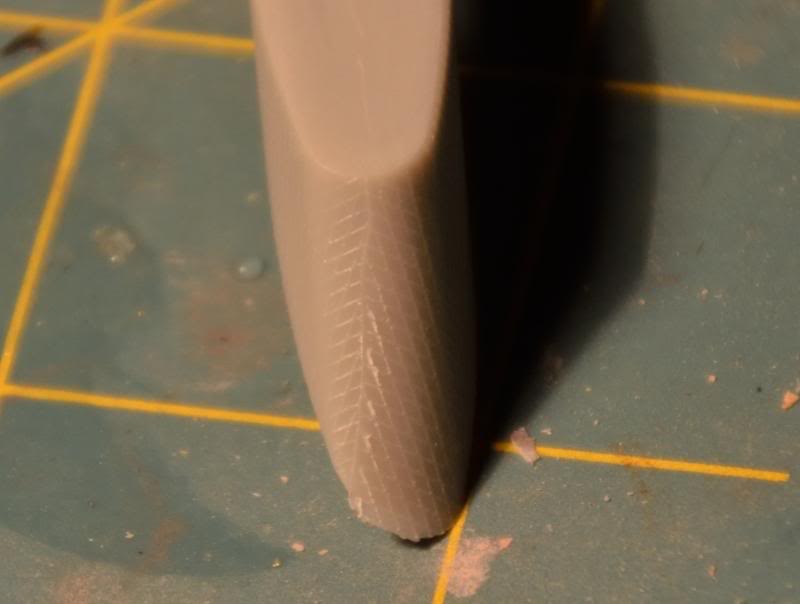
Looking at the Nacelle detail parts, there are some terrible seams and draft
angle issues. PL tried to be clever by putting a mold parting line right down
the middle her, but it resulted in a triangular line on the curve, and the line
created on the seam is pretty crappy:
Since I need 8 of these total between the two kits, I'm leaning towards fixing
and recasting them. I removed the lines on the seam and the curve the get
started. Stretched sprue should be a simple fix. In addition to the draft angle
issue, there are sinks on both sides of the front and rear, which need to be
evened out.
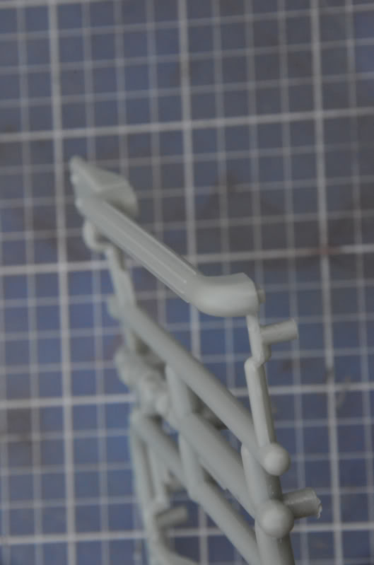
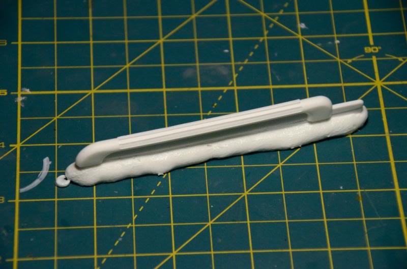
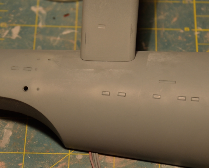
The nacelle vent detail part has an ugly seam, but it is easy to fix.
This one also hides the mold line in a raised detail line, but does a much
better job. This part also has a noticeable sink mark on the flat side
surfaces.
Some minor progress. I
restored the panel lines to part # 49, and have it primed. I also did a quick
test of my RTV before I slather it all over my one good copy.
Just to give an idea, these two shots show how bad the sink marks are on parts
#49 and parts #47
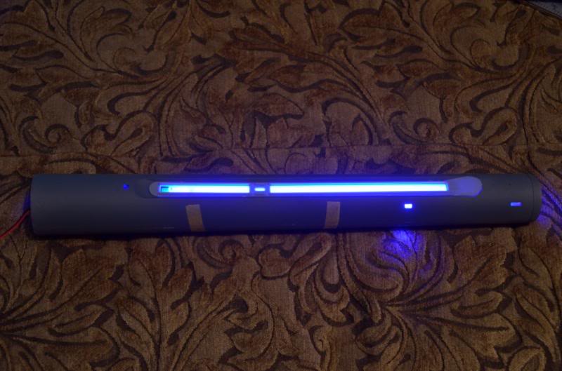
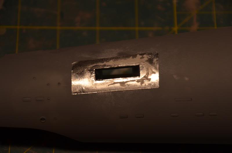
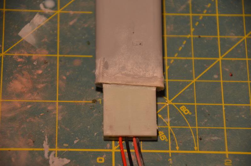
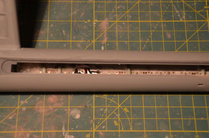
Here's a shot with the nacelle vent lights in place. I used two strings for 24
LEDs versus the full 30, which surprisingly has kept the nacelle noticeably
cooler. I have an additional set of pre wired 2 pin connectors on order (micro
mini JST 2.0 PH 2-pin, if anyone is interested) to plug into the unused 12V
plug on the board. The real trick is threading another set of 26 ga wire
through the nacelle struts. On a side note, I'm very pleased with the light
blocking from the primer and silver paint. The light diffusion is also working
wonderfully, as these LEDs are very bright. There is no hint of the individual
points.
Some minor progress. I restored the panel lines to part # 49, and have it
primed. I also did a quick test of my RTV before I slather it all over my one
good copy.
Just to give an idea, these two shots show how bad the sink marks are on parts
#49 and parts #47
Here's a shot with the nacelle vent lights in place. I used two strings for 24
LEDs versus the full 30, which surprisingly has kept the nacelle noticeably
cooler. I have an additional set of pre wired 2 pin connectors on order (micro
mini JST 2.0 PH 2-pin, if anyone is interested) to plug into the unused 12V
plug on the board. The real trick is threading another set of 26 ga wire
through the nacelle struts. On a side note, I'm very pleased with the light
blocking from the primer and silver paint. The light diffusion is also working
wonderfully, as these LEDs are very bright. There is no hint of the individual
points.
Got a little more done
today. Dug out my 50 psi pressure pot (which is not only what is needed, but
where the safety valve blows)
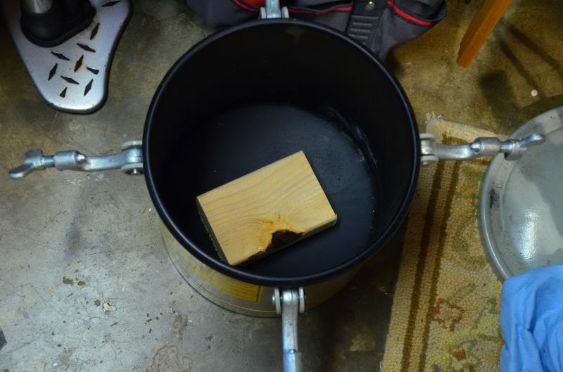
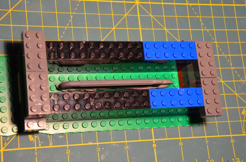
I set up part #49 in the Lego Mold of Casting, and used my LBV formula of
0.6144ml/lbv.
I let the RTV cure overnight, so we'll see what comes out tomorrow.
Here's another prime example of sink marks. Fortunately, it's just the inside
of the nacelle, and predictably at the female connector points. That said, the
issues I've pointed out so far seem to be it for molding problems. Strangely
enough, no knit lines...
The pressure pot is a
Harbor freight special, and in spite a slow leak got me through. I was able to
get a decent cast of my master for that wretched part #49. There were a number
of issues that popped up. First, the "clay" I used to make the pour
block wasn't clay, and had a bad reaction with the RTV. By bad, I mean it
prevented the RTV it touched from curing, resulting in a goopy mess.
Fortunately the reaction didn't go into the detail area, and doesn't seem to
impact the resin from curing. There are still areas that are substantially
tacky. Second, my pressure rig was acting badly. Here I was worried about the
RTV or resin being old... The pressure pot has a slow leak, a hair trigger
relief valve that blows right at 50 psi, and my compressor is now developing relief
valve issues (replacement has arrived). It was so bad my first cast was totally
screwed up. But after pummeling it into submission (ok, holding the relief
valve shut with my finger and a small amount of pressure) and adding the 2
drams of liquid resin, I finally got the good cast:
This part needs a tiny bit more cleanup, but that is definitely easier than
trying to fix those bad draft angled lines. This is dry fitted, and fairly snug
without any gluing.


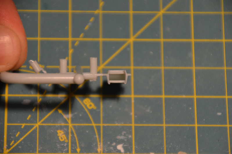
OK, work continues. First,
a nice shot of the slide mold technology used. Very impressive, and a little
frustrating it was used so sparingly. The shuttle and the impulse engines are
the two obvious places, yet the intercoolers look like crap...
No pics of the progress here, but I was able to grind down a 5 mm white LED to
fit inside the shuttle. I also wired up a white SMD (402 package) to see which
would work better. The 5 MM is snug, but much brighter. I'll have to see how
hot it gets, and if it would potentially warp the shuttle plastic. The intent
is to have the back open and the shuttle in takeoff position, so the LED would
light the windows, the open rear of the shuttle would be impossible to see and
any excess light would help illuminate the shuttle bay.
Moving on the dry fitting the lights. That was fun--not. The starboard side
neck and secondary hull windows fit for crap. I had to basically chop the large
window sections down to tiny chunks to get them to fit. On the hull side, there
were numerous window holes that weren't square or round and needed to be carved
out.
Keep in mind the above is supposed to fit as one piece...
On the flip side, literally, the port side windows fit into the neck and
secondary hull very nicely. Only 3 or so windows had flash or needed squaring.
Once I finish masking, I'll start gluing the windows in and fixing the light
block issues. Then it's wiring and off to the races.
I've also made a start on fitting the windows to the saucer. The B/C deck
windows have a significant gap at the upper edge, which was partially
alleviated by cutting off spare clear plastic on the upper edge of the window
insert. Getting them snug and flush has been a challenge. The rest of the upper
saucer clear parts have been OK, but the lower saucer windows are a mixed bag.
I think on the next kit I'll use the black or white window blanks to
effectively mask the portholes so the clear parts will fit cleaner. As is, I'll
need to use the white or black blanks to fix the B/C deck window holes which
are not very well molded.
One other observation. I'm doing up some of the Pilot version parts so I can
make a poor man's swap and pretend I have a pilot version. To that end, I
decided to do all three sets of copper parts (two production and one Pilot)
deflector dishes. To my surprise, the Pilot version dish was not fully
molded--it had a small triangular chunk missing from the outer rim. Trivial to
fix--so trivial I didn't bother to dig out my other copy--but still another
quality control issue. Not overall impressed...
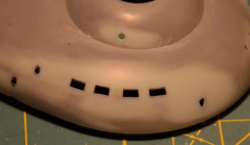
More quality issues. I'm
really getting annoyed with frankly how crappy the molding is. I've seen a
dozen or so online reviews of this kit, all gushing about how awesome a job PL
did. Well, on kit #1537, not so much. These are inserts that go along the
raised structure along the secondary hull. Note the bottom one has some missing
details in the upper right corner:
I hope I got lucky with this one--I still have one more to go.
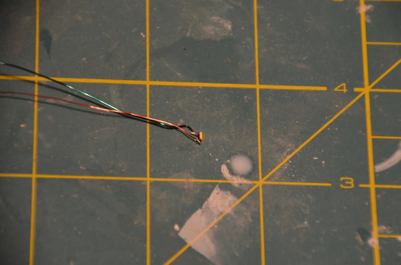
A couple of pics to follow up on the shuttle LEDs. First, the itty bitty 402
LED--now the backup:
BECAUSE I was able to sand the 5mm white LED to comfortably fit inside the
Shuttle:
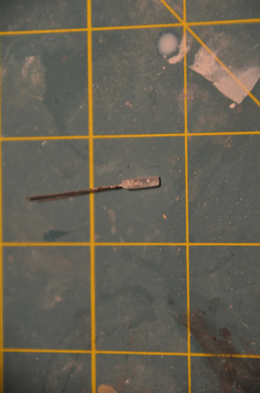
It lit up fairly well using my two hearing aid tester batteries. After taking
this much material off, it was prudent to do some testing to make sure I hadn't
toobed it. I plan to wire this in to an existing 5V line with an appropriately
sized resistor.
Don't worry Mr. Gopher, Dr's orders...
I'll use some clear smoke for the windows so they'll have some definition if
the power is off.
Large piece construction is underway. Used low temp hot glue to mount the
nacelle LED strips and secure the wiring, then put the nacelle halves together.
Part of getting to this step was running a second set of wires through the
nacelle strut (that was fun), and then taping the strut to the back or outside
of the nacelle to keep it out of the way. Though I had done some dry fitting,
there still is some gap work to deal with. I used Testors liquid cement rather
than a solvent cement due to the length of the seam. Next time I will probably
use liquid cement on the male/female peg connectors and solvent cement along
the external seams to see if that helps. The first seam to fix is the strut
receiver area, which I plan to use SGT on due to the stress of inserting the
strut. After that, the nacelle and strut become one sub assembly until final
build.
I also did a quick test of the liquid mask I applied before gluing the windows
in. Though I put some effort into getting the windows to fit, they aren't
perfect so the liquid mask peeled right off no problem. I do have a plan to fix
any poorly fitting windows post paint.
Continuing to clean up
parts. This is more for my future use-- what parts to keep an eye out for on
the next build. Here the nacelle end caps have some degree of sink marks.
Here is the worse of the two after sanding and priming.
Now I'm waiting for a replacement part for the badly molded part #20 in the
above post, and paint.
Alrighty then! Been
working on the neck lighting. The kit lighting rig would have you set one 3
pack on the bottom left, the other three pack on the top right (or vice versa),
and magically all the windows are evenly lit. Not even close. So, I tried a
different arrangement. First, I saw the neck is wide enough to mount the LED
strips facing up or down instead of sideways. The PL light kit wire clips,
however, are too wide to fit sideways. Since the clips on my wire set here in
particular was really flaky, and the LED strips are trivial to solder, I simply
cut off the clips and direct soldered the wires to the LEDs.
I then experimented with a variety of ways to mount the strips with the top one
facing down, and the bottom one facing up. This immediately gave better
lighting, but resulted in hot spots with the windows closest to the LED strips.
To remedy this, I used a couple methods. First, I painted and then puttied over
the edges of the clear styrene of the window inserts. This helped tone done the
light seeping between the window insert and the hull--not all windows are
perfectly flush as I mounted them to be flush on the outside.

Next, I mounted the LED strips to the starboard side of the neck--the side with
the female connectors. This ensured I wouldn't end up putting them in a place
that would be pinched when the halves were closed. Once again, everything was
nailed down with the low temp hot glue gun.

Finally, I realized with all the light blocking and baffling, and sheer number
of windows, trying to thread the saucer power cable through that mess AND not
running across a window was silly. Since Mr. Scott couldn't give me exact
figures, I had to make a guess as to the length to leave on either side, then
tacked it down with glue.

Results below show how they came out. Not perfect, but I'm out of time to dork
with it--and much better than the sideways mount. You really have to neck down
an camera to get close to accurate shots--anything short of a 1/200 shutter was
washing out, making all the windows look super bright and even. I'll see if I
can smooth things out a little better, especially on the foremost top row after
the glue has dried. Or those will be blacked out...


I've been working on the
mess that is the B/C deck windows. The photo below shows the gaps filled by
Milliput black (look at the upper edge of the square windows), or the misshapen
blob of a hole that was supposed to be a circle. This will be a simple fix with
SGT and a pin vise.
On to other issues, I'm curious as to how others have dealt with this terrible
seam on the impulse engines. This part was slide molded, so the presence of
this particular seam is even more puzzling. I'm likely going to grind it off
and put a scale patterned fabric replacement.
Quick update, no pics.
Chemical report--I HATE Rustoleum products in every possible way. They have an
infinite continuum of suck.
Why such rage at an inanimate object? After working the long, booooorring
nacelle seams, I switched to Bondo red glazing putty due to how much seam
filling was required. I could have blown through a tube of Tamiya putty no
problem...
Anywho, after getting the seams pretty tight, I decided to try Rustoleum filler
primer. This should have been an ideal application, given the nacelles are
perfectly smooth tubes. After a good light coat of Krylon primer to seal it up,
I put a light coat of Rustoleum on. It instantly dissolved/ate into the putty
THROUGH the Krylon.
So yes, I hate Rustoleum. I spent the next two nights fixing the seam, then
using my go to brand Duplicolor to seal the new putty, and Duplicolor gap
filler primer. Now smooth as butter, ready for paint. What is ridiculously
frustrating is I knew I was taking a risk with Rustoleum, yet I dropped $5 on a
can of crap anyways when both Duplicolor regular and gap filling primer were a
mile away at Pep Boys.
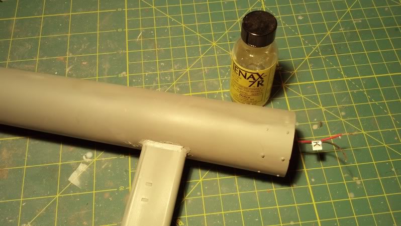
The nacelle strut to
nacelle was not as tight as I hoped. Even though the join is very strong, I
wasn't comfortable with filling a gap of this size with putty. As long as the
nacelles are, any sort of bump or torquing could make putty crack. So, I used
stretched sprue about half a mm wider than the gap, and a liberal brushing of
Tenax 7 to set it in place and then melt it enough to easily form it into place
with a #10 blade. This is the result after a skim coat of Tamiya.
Work and rework at a
snail's pace continues. In the process of test fitting the nacelle strut to the
secondary hull, I discovered the gap was surprisingly larger than expected, and
that I had made a bit of a mistake. It was the sort of mistake that had I one
available, I would have used my agonizer on myself. I was able to reduce the
seam in advance of gluing, and it was a lot easier than it should have been. My
goal is to plug the strut in and simply let the paint fill the remaining gap,
which I've gotten pretty close to.
The first step: I applied metallic tape to the secondary hull--super thin, and
impermeable. Then the foil tape was liberally, but thinly, coated with
Vaseline. Next, after fitting the strut in place, I slathered SGT around the
joint. There is no other material I could think of that would be tough enough
in this situation.
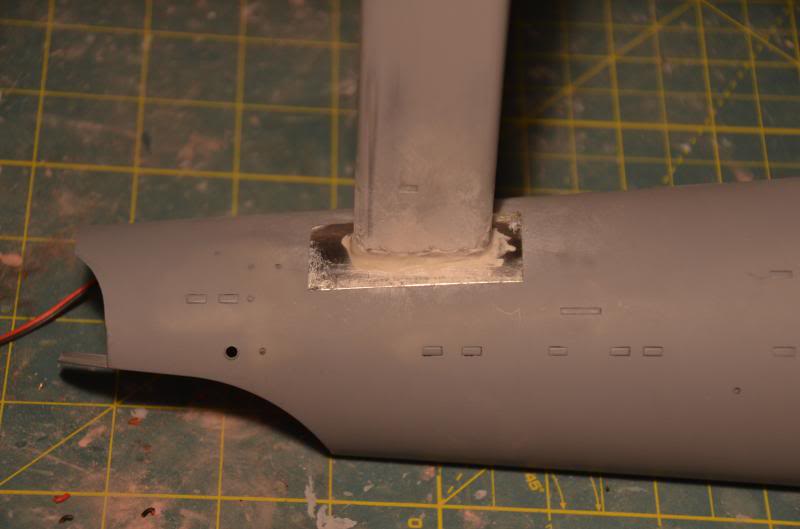
After it all cured, I could simply pop the strut off, remove the excess SGT,
and touch up and defects with putty/primer.
The finished seam is shown below. When I apply a little pressure, it actually
tightens it up some more--this is just sitting in position while I held the
camera.
On to other repairs. My
nacelle lights are comprised of waterproof blue LEDs (which means the clear
flexible layer on top) and using the spare R2 lighting kit connectors.
Well, on the starboard side, peeling off the clear layer and using the R2
connectors wasn't a problem. But, the port side vexed me. It vexed me. The
string was made up of two sets of lights, and the second, longer string kept
disconnecting. So I finally bit the bullet, and though it was already sealed
up, I popped the low temp glue gun attachments off and pulled the light string
out as much as I could through the side of the nacelle. I cut off the R2 snap
on connectors, striped and tinned the wires, and then re-soldered the mess back
together. After stuffing it all back inside the nacelle, I couldn't use hot
glue again, as the glue gun was way too big to fit through the side of the
nacelle, and simply drizzling the hot glue on the LED strip was pretty useless.
I made braces from sprue corners, and glued those around the LED strip while it
was pinched in place with a pair of pliers.
As you can see from the prices, the left side of the picture has a fairly
frosted look on the LED. This is due to CA glue fogging the clear waterproof
layer. Normally this would be bad, but it actually helps with the diffusion.
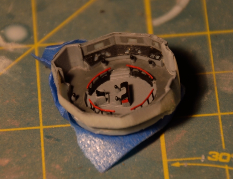
Finally put on my big boy pants
and began the bridge work. I have the Paragraphix PE set, which includes the
bridge detail masks and railings. Having three bridges to work from (two
opaque, one clear) I started surgery on a spare opaque one. I used a Dremel,
first with a standard high speed burr cutter. I found this to be hard to
precisely control without gouging the deck under the solid railing. I switched
to a bit similar to #196 in my Stylus (pistol grip Dremel):
http://www.dremel.com/en-us/tools/Pages
... x?pid=1100
http://www.dremel.com/en-us/Accessories
... px?pid=196
What I found early on is the bridge is very fragile, after sending a
seat flying...
The technique that worked best once I switched cutters was to plant the Dremel
pistol grip on my bench, and then hold the bridge floor perpendicular to the
Dremel while cutting away the rail. While this wasn't 100% perfect, it worked
much better when I switched to the clear plastic bridge due to the different
cutting characteristics. I did end up doing a little putty work to remove swirl
marks in a couple places.
As I was focusing on the opaque bridge, I worked to remove all excess material
that would diminish the lighting. Before and after:
The bottom picture also includes a healthy amount of coarse sanding stick work
to thin the remaining walls out.
Here's the bridge with the PE rails installed. I haven't done much PE work
before, but must say the Paragraphix set was very easy to work with. Most folds
could be made with tweezers or even a fingernail. Putting the railings on
bordered on trivial, aside from launching one and a daring rescue from the
carpet monster (why I have a carpet directly and only under my model desk
eludes me).
Prior to masking with tape and liquid masks, I made sure to test fit the
display PE to avoid damaging paint on the bridge or PE by post folding it.
So far I have two coats in flat black and one coat in primer gray. These three
coats do NOT provide sufficient light blocking yet which is fine, as I will
hand paint silver on the outside of the bridge when the time comes. For
lighting with the kit light holders gone, I plan instead to wrap the bridge
with white LED tape, using up to 7 LEDS to make it glow.
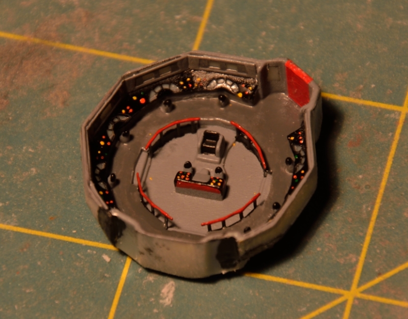
Some more ugly baby shots
of the in-progress painting. I used a base of spray paints, but brushed the
detail colors on since time is an issue. These pictures are about 4X
magnification, which really highlights every flaw. I can see Chekov's chair
needs a touch up in black. Oh well, this is the test kit anyways...
The additional knobs and buttons are painted on. Yes, I know the light layout
is fiction, but the PE set misses a whole row of buttons and knobs, so I filled
in the space. For anyone trying this at home, don't bother with red. Tiny red
dots on black don't work, but yellow, orange and green are visually distinct
enough.
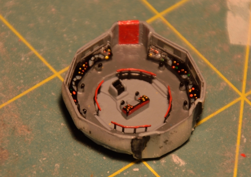
It still looks like crap without the decals or finish flat coat. I'm going with
a flat finish simply to smooth it out, and at that scale it won't matter if the
whole thing is flat anyway. I had to do a lot of brush touch up as I built it,
and flat coat will help hide that. The turbo lift doors are a chunk of red
decal cut to size. Painting it failed miserably, and I am concerned about how
well the flat coat will cover the roughness.
Next step--decals on the itty bitty screens. I'm going to pre cut them for
better fit.
Ok, last shots of the
bridge. First, with three L'Arsenal figures. Any more, and the out of scale
nature would be too obvious.
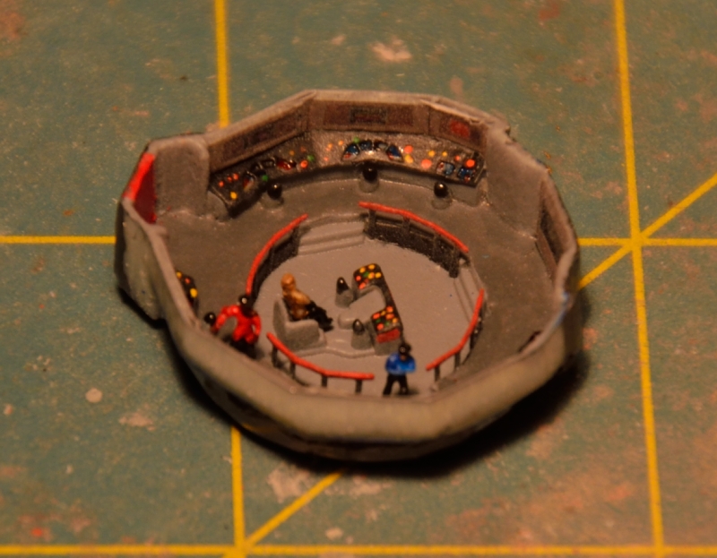
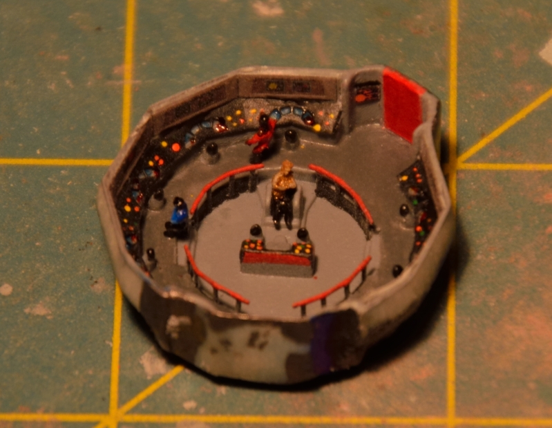
The uniforms need a little touch up, but other than that they are done. Here
are some shots of the bridge using one 3 LED strip to light up the displays.
I'll see how the kit lights compare, but am leaning towards using a three LED
strip on each side to ensure lighting is sufficient. It would be great to have
some degree of interior bridge lighting that would fit, not wash out the
backlit displays and provide general detail coverage, but I'm pretty sure that
won't be workable.
As I mentioned earlier, I found the Paragraphix decals useless for the control
panels. I instead used pin points of various Tamiya clears to give some
suggestion of color to the panels. Next step will be hard mounting the bridge
and fixing final light leaks (black Milliput will be used for both as much as
possible).
The struggle continues...3
months left to finish this puppy. And SWMBO is pressuring me like an Orion
slave girl to paint the damn thing shiny metallic. BUT, good news too--I was
able to replace a window in my garage, which is significant because now I can
set up my spray booth and exhaust fan out there (the old one wouldn't open). So
far I've been limited to quick hold-your-breath dashes (or with a respirator)
to do primer shots.
I have inflicted a little bit of delay on myself as well, by prepping the
detail parts for my second kit so I can do one round of painting for both. So
far that includes the Medium Gray engine details, minus the impulse engine
housing. I still need to cast a second set of intercoolers before I bust out
the Canadian Voodoo gray...
In the meantime, I've been working on the shuttle bay. Thank goodness I'll only
have one kit with an open bay to deal with. Gotta love prominent sink marks in
clear plastic on a visible edge...

Also have been working on the shuttle. The idea is to have one lifting off,
front windows lit. I got the LED worked out, but the light blocking tasked me.
For translucent plastic, as I saw with the bridge, you can shine a light
through it easily. BUT, because of diffusion, it is very hard to light block,
especially the tiny window frames. It would take a prohibitive amount of paint
to accomplish this. So, I went with poor man's PE--wine bottle foil.
Fortunately, I have an ample supply of wine foil due to my need to keep the
voices in my head from shouting so much.
First step was to sand off any coatings down to bare foil and flatten it out,
which is best accomplished when you carefully remove it from a bottle--it tends
to be tricky to smooth out again. I then made a 1:1 photocopy of the kit decal
sheet for the section that has the Galileo windows. I placed a small section of
smooth foil on a cutting board, then the decal print on top. Finally, I taped
both the paper and foil together to the cutting mat so nothing would move.

A steady hand, sharp hobby blade, and voila! The first one was crap. But, there
are two windscreen decals in that part of the sheet, so I started over with my
second photocopy and got decent results. After that, it was simply CA glue, and
some clean up. Partial progress shot:

After putty to clean it up a little more, the paint goes on. My initial tests
on light blocking are very promising.
Results of initial light blocking tests with paint on (the
paint doesn't contribute to light blocking at all). Next up,
decals and done.

Okay, progress worth noting! My lofty goals at the beginning
of this build have somewhat diminished in an effort to complete it. I’ve pretty
much given up on the interchangeable parts for the Production vs. Pilot
versions, and may skip moving the saucer lights on hers because she just
doesn't care.
While the base color is steel, the accent parts such as intercoolers and other
details will be in their original colors, so we'll see how that works out. The
other visible details, such as the bridge and open hangar bay, will also be
done up old school. The final metallic she chose was Duplicolor Stainless
Steel, used for automotive trim. It goes on very flaky, as in the surface will
look like 60 grit sandpaper:

After giving it an hour or so to cure, you can buff it with a tee shirt. I used
a shop towel, then a light wet sand with 4000 grit sandpaper to achieve this:

What is exceptionally cool about this particular paint is that while it has an
old school spray bomb nozzle (not the finer mist rectangle nozzle), it can
recoat like a lacquer primer, and leaves NO recoating edge at all. I did some
test shots on the nacelles, using Stainless steel and Duplicolor Platinum, and
the Platinum shade looked like you'd expect a metallic from a can--high shine
areas, blotchy, obvious recoat edges, spattering, etc. SS has none of that and
is perfect for what I need. I haven't checked it yet for light blocking, but as
a metallic flake paint I expect it can only help in that regard.
Since I recently completed soldering up the upper and lower saucer wiring
harnesses, my goal this weekend is to get the sauce together and then paint.
I'm really incentivized to get this done now that I have a working Arduino
prototyping board on hand, and can work on building a custom light scheme for
MY Enterprise.
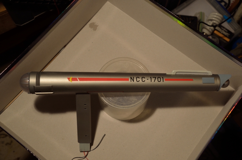
Okay, last bit from the Columbus Day holiday weekend.
After seeing how the metallic paint overlays, and edges disappear when hit with
flat coat, I decided to build the saucer sections, paint, decal and flat coat
the halves then install glass and glue. Below, the bottom half:

An issue comes from how rough the metallic surface is. This is the unbuffed
secondary hull ring.

Even after buffing and a quick wet sand with 6000 grit cloth you won't get a
glass smooth surface. For flat areas like the nacelles, this was no issue as
the decals responded to Micro Set & Sol. The one bit of silvering was
remedied using the "aggressive" approach from below.

Note the gray accent decal is essentially invisible against the stainless steel
finish.

On the saucer I had to resort to a different strategy for the rougher finish
and grid lines. Dousing decals in Sol wasn't doing squat. So I took a more
aggressive approach.

I've done this before, so I knew it would work...if great care is taken. First,
you get ONE pass at best with the brush. Second pass, you have just melted a
decal (look at the nearest "C" in the saucer picture up top). Second,
these are ridiculously simple decals. Where I did melt the decal, it was on a
solid black portion, trivial to repair. Third, I knew the glue would NOT damage
the base coat as it was a lacquer.
This did work to snuggle/melt the decals into the grid and eliminate silvering,
but isn't ideal. For the saucer top registry numbers, I laid down a base coat
of Future. So, that's the next one and only one chance experiment!
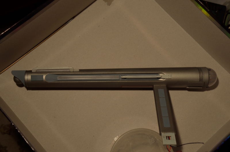
Another minor update--added the light blue to the neck:
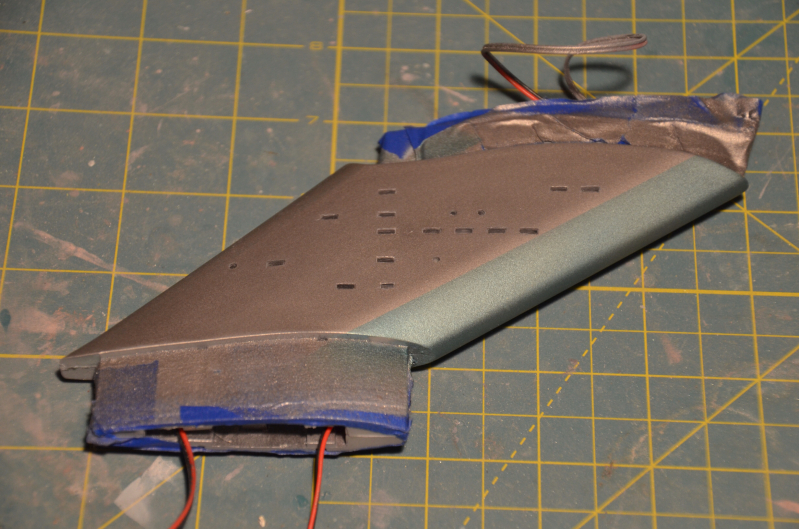
This was done with Alclad Hot Metal Blue.
I also removed the masking from the windows, and that was not as wonderful as I
hoped. Next time, I'll paint then window then seal.
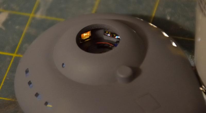
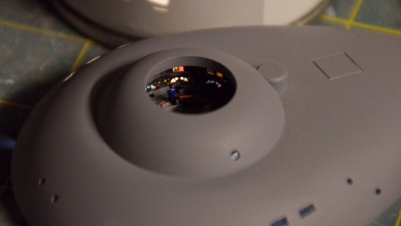
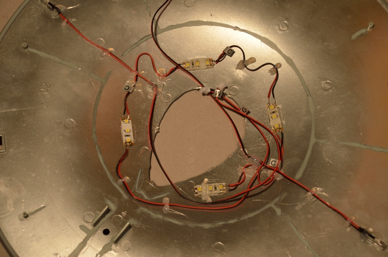
As previously mentioned, the unplanned benefit of my saucer
glue masking scheme in action (recall I used liquid mask to keep the interior
seams free of light blocking paint). Turns out the paint free lines were critical
when laying out the wires to ensure I didn't create a pinch:
My collection of completed parts now includes the bridge dome, the neck, and
the two nacelles, with the saucer soon to follow:
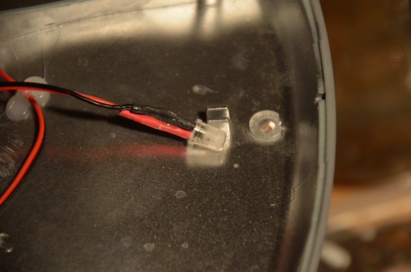
On to more work, and a near disaster. As the kit port saucer
strobe LED was bad, I replaced it with a Radio Shack standard 5mm white LED.
Since these LEDs are highly directional, I flattened the tip and scuffed the
sides with. 320 grit sanding stick. This gives it a near uniform glow, lighting
the strobes quite nicely.
Now the near disaster. I was about to glue the saucer
shut, and thought "Aha! I forgot to run the neck wire "H" into
the saucer from the neck." So thinking I had caught a major mistake, I
glued the neck onto the lower saucer half. I connected "H", and set
some tape to hold the neck in place. Then off to watch the tube with the
wife...
Coming back 2 hours later, I found the tape, due to the angle of the neck, had
pulled the front of the neck away from the saucer horribly. Fortunately, the
glue wasn't quite set due to the cold in the garage, so I doused the inside of
the neck/lower saucer joint with Ambro Pro-Weld and was able to loosen up the
previous glue enough to adjust the angle (spilling Ambro all over the place in
the process, greatly limiting my work space...). Using my hands I could force
the joint closed, but as soon as I let go it opened up again. Panic time. I
broke a hobby bar clamp trying to get enough pressure on the joint, so I
wrapped the neck piece with a shop towel to protect the paint and got a real
wood working bar clamp on it. I clamped it down until the saucer
and neck were flush, which was a trick because the clamp and neck angle kept
pulling the saucer off the edge of the work bench...
That did the trick, but I had to be careful, as this clamp would easily crush
through even this beefy kit if I gave it too many turns. Overall there was some
minor paint damage from glue spilling, but the dozens of coats of dull coat
kept it mostly together, and from my earlier experience I can touch the damage
up fairly easily with a brush. Now on to gluing the saucer top on, and reducing
my part count from 3 to 1!
BIG DAY. The
saucer is now together on the pylon, and the glue is curing.
While my sanded and scuffed Radio Shack special LED was doing an OK job
replacing the omni port side strobe, the light there wasn't as bright as on the
starboard side. First order of business was to add reflectors of tin foil to
help the situation. The foil is actually angled somewhat upward (downward in
the picture) to focus as much light to the top side strobe without messing up
the side or bottom strobes.

Here's where the liquid masking tape I used for the saucer top really came in
handy. The final wire layout to snug things down was relatively painless to
route, as the "stay out" zones were clearly marked--especially around
that "W" shaped structure near the pylon. A lot of wiring goes
through a tight spot there.

Here's the bottom saucer half final layout (except the three loose Bridge
lights, which will be finalized later). These are as much for my future
reference when I build ship #2.

Then came the obligatory anal-retentive final this is it light check. As I had
glue gunned down the saucer top wires fairly tightly to avoid any possibility
of pinching the slack, they were loosely plugged in. I had them so short in
fact I had to apply all the glue before final connecting them. These photos are
pretty accurate as to light intensity; you can see the foil reflectors on the
port (red) side strobe are working quite well. I'm really pleased with how
bright the tiny outside most strobes came out, as they can be hard to evenly
light.

Some "into Darkness" action:

And every hobby/plastic jawed spring clamp I could find...

I was a little surprised at how "gappy" the saucer halves could get,
and even with all the alignment pins and internal structure there was a lot of
slop in the fit. You really have to be careful to align top and bottom
gridlines all the way around.