Resin
Joint Covers
 One of the biggest
problems with the appearance of HG kits (either 1/144 or 1/100 scale) is the
use of polyvinyl (PV) joints. The PV
joints allow the arms and legs to move and not wear out. Unfortunately, PV is incredibly difficult to
paint or even cleanup. Since PV is
"slick" and flexible, paint tends to flake off in large chunks. Since it is also somewhat rubbery it is very
difficult to remove mold lines or other manufacturing flaws--cleanly cutting
and smoothly sanding are nearly impossible.
Glue, even superglue, does not stick to PV so it is essentially
impossible to add mechanical details to a PV joint.
One of the biggest
problems with the appearance of HG kits (either 1/144 or 1/100 scale) is the
use of polyvinyl (PV) joints. The PV
joints allow the arms and legs to move and not wear out. Unfortunately, PV is incredibly difficult to
paint or even cleanup. Since PV is
"slick" and flexible, paint tends to flake off in large chunks. Since it is also somewhat rubbery it is very
difficult to remove mold lines or other manufacturing flaws--cleanly cutting
and smoothly sanding are nearly impossible.
Glue, even superglue, does not stick to PV so it is essentially
impossible to add mechanical details to a PV joint.
To overcome this
problem, you have to eliminate the polyvinyl from the areas you wish to paint
but keep PV at the actual joint. A lot
of times this is done by building joint covers out of thin sheets of
styrene. I find this method to be
incredibly tedious. It is difficult
enough to create one joint cover for a 1/144 scale elbow; making a second
matching one simply takes too much of my time.
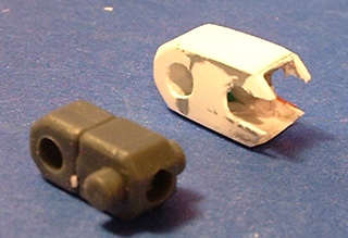
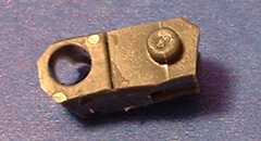
The picture to the right is an elbow PV cover I made for a 1/10
kit. It took about 5 hours over the
course of a couple days to get it done—and that was the first one of two….
My alternative solution involves using RTV to copy the PV joint
and then encapsulate the PV in resin.
The process is this:
 1. Assemble, if
necessary, the PV joint pieces. Try to
cleanup as much as possible any mold flaws.
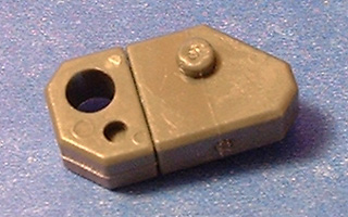
In this example, I am using the two-part knee joint for the 1/144 scale
HG Gouf Flight Type. As you can see in
the picture, the upper portion of the knee joint has a hole through it where it
mounts onto the thigh. It also has two
pegs for the lower leg mount. Using
clay, I filled in the seam line between the two PV pieces as well as the small
circular hole by the thigh pivot. I
also partially filled in the middle of the large hole for the thigh
pivot. I am using a 1-piece mold to
copy the joint so a hole completely through the part would make it impossible
to remove from the mold.
1. Assemble, if
necessary, the PV joint pieces. Try to
cleanup as much as possible any mold flaws.
In this example, I am using the two-part knee joint for the 1/144 scale
HG Gouf Flight Type. As you can see in
the picture, the upper portion of the knee joint has a hole through it where it
mounts onto the thigh. It also has two
pegs for the lower leg mount. Using
clay, I filled in the seam line between the two PV pieces as well as the small
circular hole by the thigh pivot. I
also partially filled in the middle of the large hole for the thigh
pivot. I am using a 1-piece mold to
copy the joint so a hole completely through the part would make it impossible
to remove from the mold.
 2. Make a mold of the PV
joint. For this piece, the mold was
made with the joint vertically oriented.
The extended pegs were up, and the thigh mount hole was at the bottom as
I poured the RTV. I made the sidewalls
(where the pegs stick into) of the mold fairly thin, and used Legos to make the
mold walls. A flat, fairly thin and
even mold wall is the key to this working. When the mold was completed, the
pegs were at the bottom and the thigh mount hole is near the top where the resin
will be poured in. If you were to pour
resin into the mold right now, you should get a perfect copy of the original PV
joint including the extending pegs and an indentation on both sides where the
thigh hole would be on the original. In
the image to the right, the blue arrow pints to the indent for the upper thigh
hole. How you orient the part in the
mold depends on how the part is shaped, and will vary.
2. Make a mold of the PV
joint. For this piece, the mold was
made with the joint vertically oriented.
The extended pegs were up, and the thigh mount hole was at the bottom as
I poured the RTV. I made the sidewalls
(where the pegs stick into) of the mold fairly thin, and used Legos to make the
mold walls. A flat, fairly thin and
even mold wall is the key to this working. When the mold was completed, the
pegs were at the bottom and the thigh mount hole is near the top where the resin
will be poured in. If you were to pour
resin into the mold right now, you should get a perfect copy of the original PV
joint including the extending pegs and an indentation on both sides where the
thigh hole would be on the original. In
the image to the right, the blue arrow pints to the indent for the upper thigh
hole. How you orient the part in the
mold depends on how the part is shaped, and will vary.
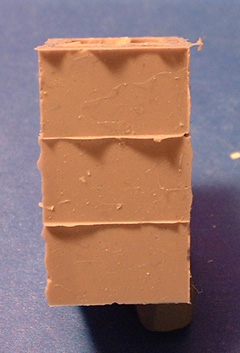
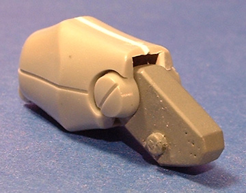
 3. Using a very sharp
razor blade or hobby knife, carve away all of the excess PV except around the
joints and what is required to hold the two pieces together. This picture shows how chopped down you can
get a joint. I focused on removing as
much PV from the outer surfaces as possible.
The intent is when this part is placed in the mold there should be huge
gaps between a mold interior and the joint.
Those huge gaps are where the resin will go.
3. Using a very sharp
razor blade or hobby knife, carve away all of the excess PV except around the
joints and what is required to hold the two pieces together. This picture shows how chopped down you can
get a joint. I focused on removing as
much PV from the outer surfaces as possible.
The intent is when this part is placed in the mold there should be huge
gaps between a mold interior and the joint.
Those huge gaps are where the resin will go.
4. Prepare resin and pour into the mold. I would fill the mold at least half full. Now comes the tricky part: stick the remains of the PV joint into the mold. Here is where the thin mold wall, extended pegs and the thigh mount hole will help you. You want the PV pegs to fit into their matching holes in the mold wall, and you want the PV hole to match up with its proper position too. When you put the PV remains into the mold, if the pegs on the bottom do not properly seat into the mold, the mold wall will bulge out. In the image to the left, the arrow points to where the peg is in the mold—not where it is supposed to be. On the right, the mold walls are flat, indicating the PV is seated. Once you get the PV properly into the mold, the mold will become perfectly flat, smooth and even on the outside. You can try pouring the resin after seating the PV, but it is very hard to completely fill the mold with the PV in place.
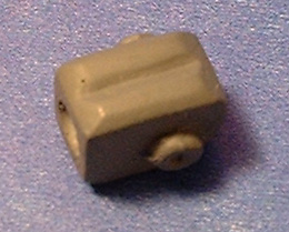
5. Remove the
cured resin from the mold. If
everything went well, you now have a resin shell completely 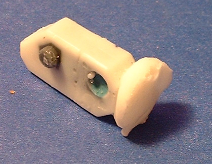 covering
the PV joint—except where you really want PV so the joint can move. The picture shows the extending pegs are
clean of resin, so they lined up perfectly in the mold. The upper thigh hole also is fairly clean,
so the mold indent matched there as well.
The blue in the upper thigh hole is the clay I used to make sure the RTV
didn’t go completely through so I could remove it from the mold. Leaving the clay in place for the casting
makes cleanup a bit easier, since the resin would otherwise fill the hole. And there is some cleanup here: the excess resin needs trimming, the thigh
hole needs to be drilled through and the molding flaws need cleanup. The good news is you CAN clean up the mold
flaws—resin is very easy to sand, shape, superglue mechanical details
to—whatever. And of course, paint will
now stick to the joint. Shown below is
the result on a 144 elbow joint—the original, and 2 shots of the resin coated
and primed finished part. In the case
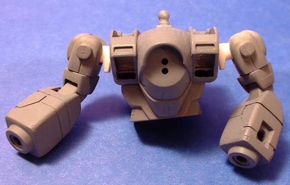
of the 1/100 elbow joint at the top of the page, I made a mold of the joint
cover and PV, and then used steps 3-5 to encase the elbows in resin. I was NOT going to make another one of those
stupid things!
covering
the PV joint—except where you really want PV so the joint can move. The picture shows the extending pegs are
clean of resin, so they lined up perfectly in the mold. The upper thigh hole also is fairly clean,
so the mold indent matched there as well.
The blue in the upper thigh hole is the clay I used to make sure the RTV
didn’t go completely through so I could remove it from the mold. Leaving the clay in place for the casting
makes cleanup a bit easier, since the resin would otherwise fill the hole. And there is some cleanup here: the excess resin needs trimming, the thigh
hole needs to be drilled through and the molding flaws need cleanup. The good news is you CAN clean up the mold
flaws—resin is very easy to sand, shape, superglue mechanical details
to—whatever. And of course, paint will
now stick to the joint. Shown below is
the result on a 144 elbow joint—the original, and 2 shots of the resin coated
and primed finished part. In the case
of the 1/100 elbow joint at the top of the page, I made a mold of the joint
cover and PV, and then used steps 3-5 to encase the elbows in resin. I was NOT going to make another one of those
stupid things! 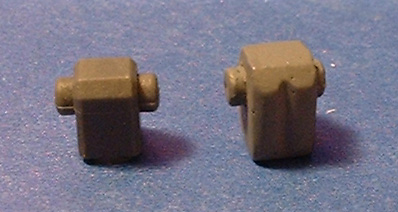
As I said earlier, nothing really sticks well to PV—even resin. This is why you have to completely encapsulate the joint in a single piece shell for this process to work. If the shell isn’t one piece, it can break off or chip away like paint would. If the resin shell is too thin, or cracks, it can be repaired with SGT quite easily. And if the PV piece lets totally messed up in the mold and the pegs/holes end up in the wrong places? Since resin doesn’t stick to PV, just crack the shell, remove the PV and start over. The piece shown here was my second attempt—the first time I didn’t properly line up the pegs, and the whole thing was off (I should have known—the mold wall had a bump in it because the pegs hadn’t matched up with the mold right). I used a pair of pliers to destroy the resin shell, started over and was done.
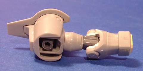 Here
are the final results for the Gouf Flight Type elbow and knee. For the elbow, the resin PV cover was
extended beyond the regular elbow PV to improve the arm flex. The sides of the forearm were filled in with
0.30” styrene for a snugger fit. The
knee is nearly identical to the original PV, since it is almost totally hidden
by the lower leg when the kit is finished.
Since the majority of the knee block is resin now, I can easily drill
through it to run wiring to the LED monoeye I am installing. The little extra effort in making these
joint covers really pays off in a number of ways.
Here
are the final results for the Gouf Flight Type elbow and knee. For the elbow, the resin PV cover was
extended beyond the regular elbow PV to improve the arm flex. The sides of the forearm were filled in with
0.30” styrene for a snugger fit. The
knee is nearly identical to the original PV, since it is almost totally hidden
by the lower leg when the kit is finished.
Since the majority of the knee block is resin now, I can easily drill
through it to run wiring to the LED monoeye I am installing. The little extra effort in making these
joint covers really pays off in a number of ways.
Another joint I’ve used this trick on is from the picture at the top of this page. This is a standard 1/100 HG elbow, seen in the Gundam Wing and Gundam X kits (there may be others too). The 2 pieces allow the arm to flex and the lower arm to swivel. For Wing Gundam Zero, I put a swivel joint in the upper arm so I could make the elbow PV cover one piece. After scratch-building the one cover from thin sheet styrene, I wasn’t going to go to all that trouble again! The results are a heck of a lot better than the raw styrene.