Epyon
(or how to spend 4 months on modifying one HG kit and
still care enough to make a web page)
Overall: Not good.
Without some serious work, Epyon is a "single view" kit--it only
looks good standing straight up, from the front and the viewer’s eyes level
with the chest. If you are looking at
Epyon from the sides, rear or the front looking even slightly down, then
"yuck". The knee joint to the
lower leg is completely hollow & see-through. The transformation mechanism to mobile armor (MA) mode is
completely exposed, which lets you see how hollow the kit is in either
mode. In MA mode, the very first things
you see are the exposed PC cap ankle joints and how hollow the legs are. The heat rod is made up of plastic on
plastic joints that will wear out. The
shield has no internal details. The
maroon plastic the kit is mostly molded in tends to scar when sanded.
Any
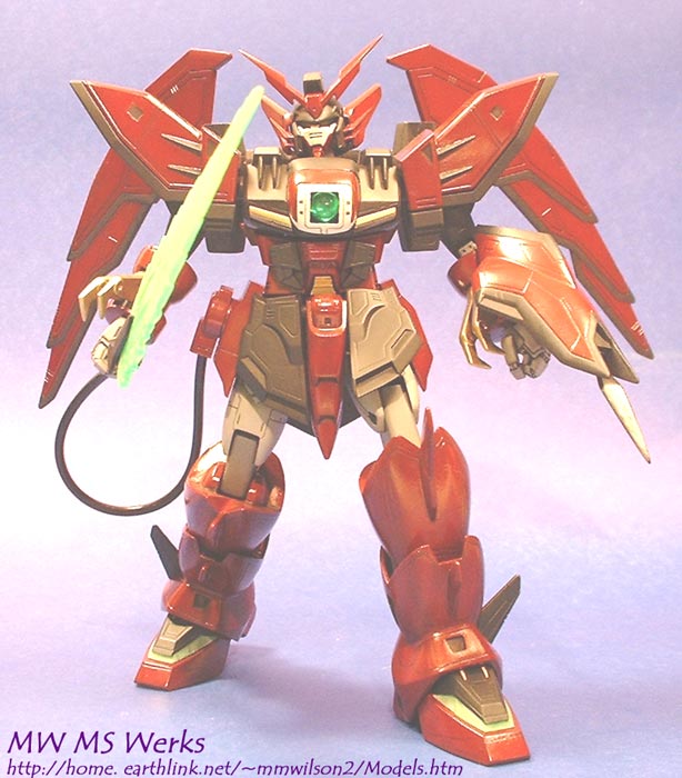
high points? Epyon's menacing
bulk. Epyon is one of the 800 lb
gorilla of GW Gundams (Wing Zero is the other). Compared to the other GW 1:100 kits, Epyon should be noticeably
beefier than the others, and it come through.
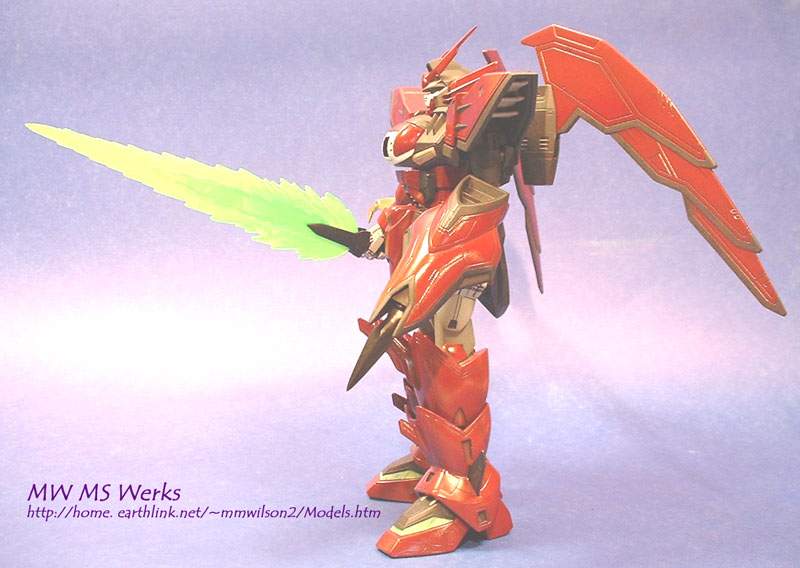
The "Most Excessive Beam Sabre" is well done, and the heat rod
spike & shield look good from the front.
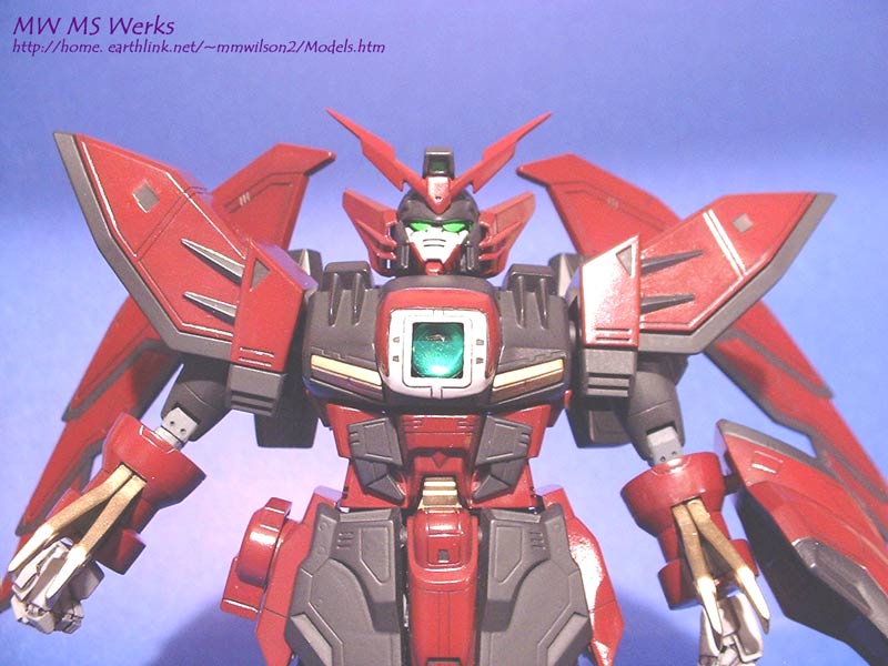
The head & face are also well done, and the kit is molded in fairly
accurate colors for the non-painting crowd.
 Legs: Easily the weakest part of this kit. The legs are unique by having an extra joint
in the middle of the lower leg. It is
the joint we all call the knee, though, that is the major problem on this
kit. The upper leg is standard fare for
a GW 1:100 kit, and the knee block plugs into it nicely. However, the hinge PC cap on the lower knee
joint is totally exposed. When the knee
block is plugged in there is a noticeable gap between the knee block and the
lower leg. The gap is so bad that you
can see completely through the leg below the knee block. The plastic PC cap
hinges are also completely hollow.
Without trying too hard, anyone looking at Epyon's legs from behind or
slightly down from any side can see through the knee joint and down into the
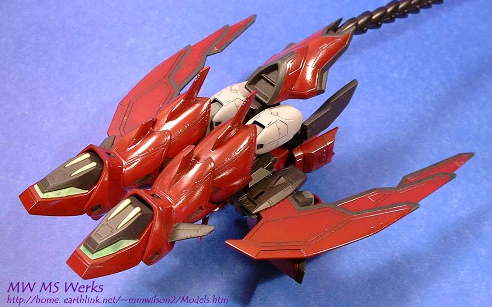
hollow lower leg. In mobile armor (MA)
mode, there is another leg related problem.
Epyon essentially folds in half backwards with the legs folding over the
back so the feet are the very front of the vehicle. The feet fold in half so the toes and heels point forward. When done, the ankle joint PC cap is completely
exposed and looks toyish. Finally, the
legs also have a ton of very fine panel line details. Cleanup of the seam lines is a considerable pain in the
butt. The reddish plastic the legs are
made of is hard to sand and carve--it tends to shred when sanded.
Legs: Easily the weakest part of this kit. The legs are unique by having an extra joint
in the middle of the lower leg. It is
the joint we all call the knee, though, that is the major problem on this
kit. The upper leg is standard fare for
a GW 1:100 kit, and the knee block plugs into it nicely. However, the hinge PC cap on the lower knee
joint is totally exposed. When the knee
block is plugged in there is a noticeable gap between the knee block and the
lower leg. The gap is so bad that you
can see completely through the leg below the knee block. The plastic PC cap
hinges are also completely hollow.
Without trying too hard, anyone looking at Epyon's legs from behind or
slightly down from any side can see through the knee joint and down into the
hollow lower leg. In mobile armor (MA)
mode, there is another leg related problem.
Epyon essentially folds in half backwards with the legs folding over the
back so the feet are the very front of the vehicle. The feet fold in half so the toes and heels point forward. When done, the ankle joint PC cap is completely
exposed and looks toyish. Finally, the
legs also have a ton of very fine panel line details. Cleanup of the seam lines is a considerable pain in the
butt. The reddish plastic the legs are
made of is hard to sand and carve--it tends to shred when sanded.
The
knee fixes: I tackled this one
first, since Epyon will be in mecha mode the most. There were 2 issues I felt needed work. The biggest job is walling off all the open space around the
lower knee hinge. I used sheet styrene,
putty and SGT, but
anything is better than the kit as is.
Milliput was used to fill in the "kneecap" area, but SGT would
work as well. This simple fix is in my
opinion the best, easiest fix for improving Epyon's standing mode.
The
second fix was the knee block cables.
Each knee block has 2 upper and 2 lower plastic cables on the back. These cables effectively make it impossible
to clean up the seam down the middle of the knee block, and look plain
cheesy--too plain, too short. I cut
them off, sanded the stubs flush, and drilled 1/16" holes where the cables
were. I found some neat 2 mm diameter
metallic braided hose in the local hobby shop car section that was a perfect
fit in size and appearance, and super glued it in. The metal braided hose is flexible, but can be bent into a curve so
the ends can be hidden inside the leg.
If metal hose isn't available, thin shoelaces (like for dress shoes) can
also be used; with silver paint and a black wash it will look fine.
The
ankle fix: I considered a number of
options to deal with MA mode foot problems.
One was heavily detailing the inside of the leg and top of the foot to
hide the foot joint polycap. This
involves a huge amount of effort for something rarely visible. After reviewing the April 2001 Hobby Japan
Gouf Custom (GC) article, I found a solution that is a lot more
functional. The GC has a reversed ankle
joint from the Epyon kit--the ball is on the leg, the socket is on the
foot. In the article, the fixed ball
joint was replaced with a ball on a shaft, which was mounted to slide through a
standard PC hinge. This allows you to
rotate the ball front to back, but more importantly to slide the ball in and
out from the ankle. By moving the ball
out, more dramatic foot/leg poses can be made--less foot/leg interference. For Epyon, by moving the foot in, the
exposed ankle joint is completely hidden.
 To do this, I used 2 Kotobukiya 102B
joints and 4 matching PC hinges (from spares).
First step: replace the kit foot ball with the102B socket. The ball was cut off
To do this, I used 2 Kotobukiya 102B
joints and 4 matching PC hinges (from spares).
First step: replace the kit foot ball with the102B socket. The ball was cut off 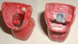 the
heel and the area below hollowed out.
The 102B socket cup has 3 prongs--2 on the side, 1 on the top. The two side prongs were cut off and the top
prong was heated with a candle just until it began to melt. I used a razor blade to flatten the molten
prong end into a mushroom shape. This
created an anchor I could use SGT to glue the socket
into the heel cavity since it wouldn't stick to a smooth PC shaft. Since then, I have also modified my Altron ankle
joints with a similar solution.
After placing the sockets into each heel, I encapsulated the socket
outside with SGT, which was shaped to hide the socket.
the
heel and the area below hollowed out.
The 102B socket cup has 3 prongs--2 on the side, 1 on the top. The two side prongs were cut off and the top
prong was heated with a candle just until it began to melt. I used a razor blade to flatten the molten
prong end into a mushroom shape. This
created an anchor I could use SGT to glue the socket
into the heel cavity since it wouldn't stick to a smooth PC shaft. Since then, I have also modified my Altron ankle
joints with a similar solution.
After placing the sockets into each heel, I encapsulated the socket
outside with SGT, which was shaped to hide the socket.
The
other half of the joint, the ball side, is more complicated; you will need to
build a pivot point to hold the new PC hinge.
The starting point is to remove all of the lower leg internal structure;
I used a Dremel tool with a large ball cutter. This includes the ankle joint socket holder, all the lower leg
snap connector structures and the box inside the leg for the side fins. If any of this is left in place, the foot
won't retract all the way. Next, assemble
the 102B ball joint shaft/PC hinge, and put the leg connector joint PC in place
on one side. When in MA mode the ball
joint shaft will retract through the leg connector joint and into the upper leg
segment. Hold/tape the ball joint
shaft/PC hinge (with the ball down) directly in line with and about 2-3 mm
(from top of new PC hinge to bottom of leg connector PC) below the leg
connector joint PC. I used SGT to build
up a joint from the leg wall to the PC 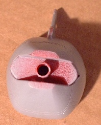 hinge pivot, making sure the hinge is aligned.
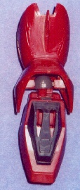
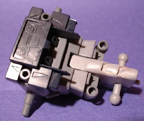
 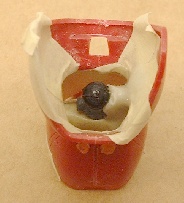 The picture on the far left shows the ball joint connector, leg
connector joint PC and the new ankle hinge with one side built-up in SGT. Tape
the other leg half on, making sure it is lined up, and then build up the other
half of the joint
The picture on the far left shows the ball joint connector, leg
connector joint PC and the new ankle hinge with one side built-up in SGT. Tape
the other leg half on, making sure it is lined up, and then build up the other
half of the joint 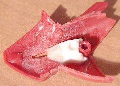 pivot with SGT. I chose to make a master and resin copies--the
lower legs are symmetrical. Before
applying the SGT, I put masking tape on the inside of the leg so the SGT would
come off.
pivot with SGT. I chose to make a master and resin copies--the
lower legs are symmetrical. Before
applying the SGT, I put masking tape on the inside of the leg so the SGT would
come off.
Once
the SGT is cured, you can take apart the leg and clean up the pivot. Even if you do not make copies, removing the
pivots makes cleanup easier. The main goal
here is to make sure the pivot is clear; it doesn't need to look good since it
is supposed to be hidden.
One last step is to drill out the peg
connecting the leg segments. Using a
1/8th inch bit, the peg can be drilled out enough for the ankle joint
shaft to retract into. This will leave
a thin wall on the peg that looks flimsy, but is actually very strong if the
wall is intact. A safe way to drill out
the peg is to leave the PC hinge on the peg--the PC will keep the drilling
stresses from destroying the peg and use smaller drill bits for the first cuts,
working your way up to the 1/8th inch bit. If the peg is somehow trashed, you can encapsulate the PC hinge
with SGT and trap it to the lower leg or rebuild it with SGT. When done with cleanup, all that is left is
gluing the leg parts together. At this
point, the foot can be extended for standing or folded and retracted for MA
mode. The images below show the leg
interior with the leg extended in normal and MA modes. Since the black ABS peg in the photos below
is shorter than I really wanted, I cast a new pair of pegs from reinforced
white resin.
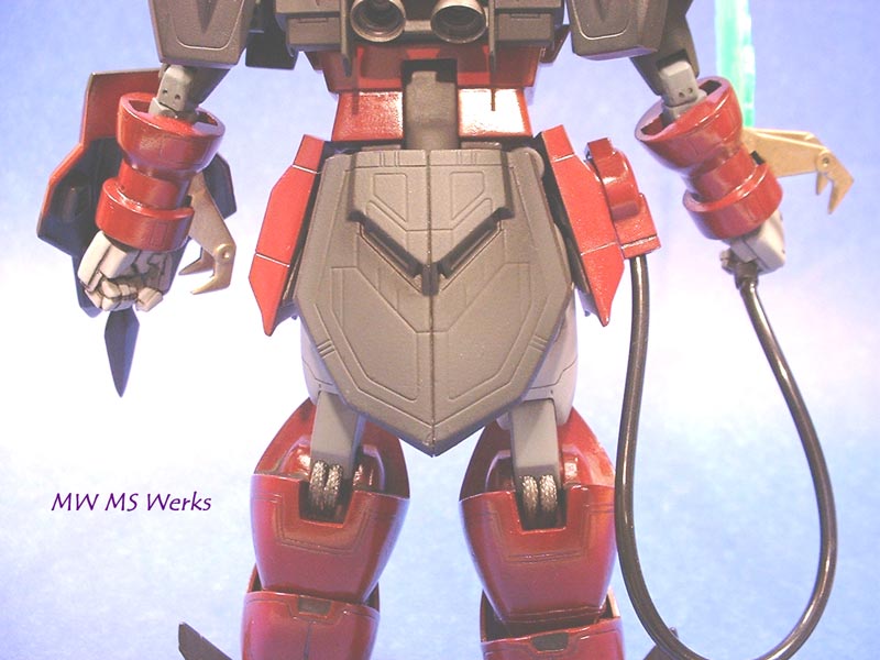
Arms/shoulders: The arms are standard for GW HG 1:100, with one notable exception. Epyon has a couple gold-plated claws in the middle of each forearm for MA mode, which complicate construction & painting. Being a standard GW HG, it has a 2-part exposed PC elbow joint. The upper PC is very visible; the lower is buried in the elbow. I roughed the upper PC, applied SGT, and shaped a joint cover with a few details. On the lower elbow PC, the hinge point is exposed similar to the lower knee joint hinge, but better hidden. The area on the sides of the PC was filled in with Milliput to hide the hinge, and SGT used to make a joint cover.
For the claws, I stripped off the cheese-ola one-sided gold chrome with E-Z Off and repainted the claws with Model Master Bright Brass. Once assembled, they were masked with Masking Sol to protect them while the forearms were being built. The Masking Sol unfortunately turned to goo and trashed the brass paint job, requiring a complete repainting of the claws after the forearms were completed and painted.
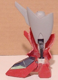
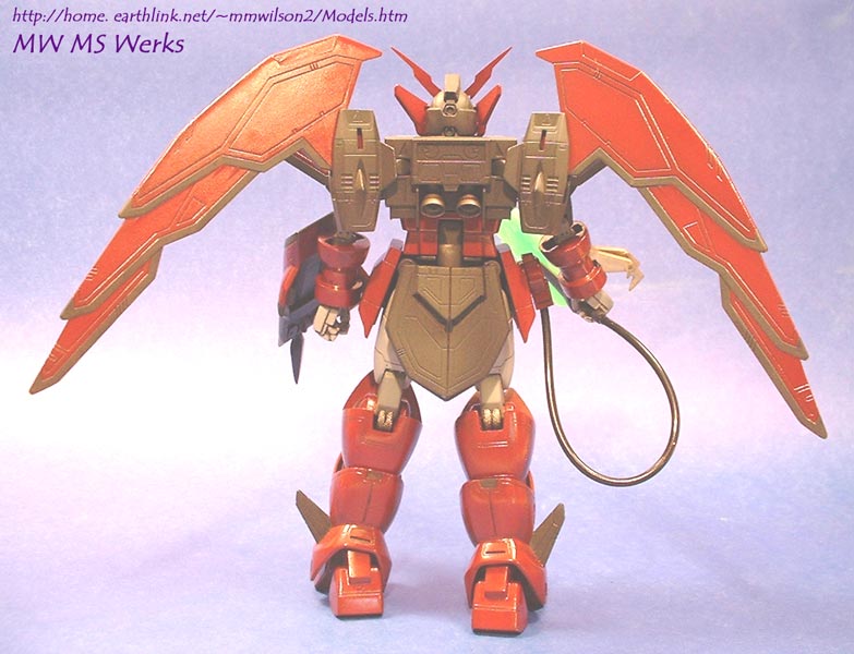
 Torso/hips: Epyon has an interesting MA
transformation. The rear hip armor
skirt splits down the middle, and the rear of the crotch including the legs
folds 90° up so the hip is moved to the middle of the back. Essentially, Epyon's lower abdomen and butt
are turned inside out. The result is
about as attractive as it sounds. The
inside of the hip armor plates are unfinished.
The crotch, both the stationary and the rotating pieces, are
hollow. The rotating portion hinges in
the middle of the back, so there are a lot of gaps that let you see into the
rear of the torso.
Torso/hips: Epyon has an interesting MA
transformation. The rear hip armor
skirt splits down the middle, and the rear of the crotch including the legs
folds 90° up so the hip is moved to the middle of the back. Essentially, Epyon's lower abdomen and butt
are turned inside out. The result is
about as attractive as it sounds. The
inside of the hip armor plates are unfinished.
The crotch, both the stationary and the rotating pieces, are
hollow. The rotating portion hinges in
the middle of the back, so there are a lot of gaps that let you see into the
rear of the torso.
Recommendation? Kill the transformation mechanism--Epyon is only seen once or twice in MA mode anyway. Glue the crotch pieces and rear hip armor plates together. Wall off the back of the torso with styrene or putty (don't use toluene based putty--too large). Don't worry about the crappy exposed ankle PC joint in MA mode. Fix the knees, stick a fork in it--it's done.
What did I do? Fixed it, mostly. The two crotch pieces were filled in with Milliput. A "spine" was sculpted onto the outside of the rotating crotch. The hip armor skirt pieces were completely filled in with detail scribed in. I normally build a framework to detail the inside of GW hip armor skirt plates. Since Epyon is a brutish MS, I thought solid hip armor plates would match the overall design better than hollow plates with an interior frame.
The hinges for the split rear armor skirt look incredibly fake, flimsy and non-functional. Since I planned on keeping Epyon in MS mode most of the time, I white-glued the 2 rear armor skirt halves together and made a RTV mold. With this I cast a one-piece resin rear armor skirt. The solid rear armor skirt simply plugs into kit hinge mount points with adapters made from SGT, which is substantially more beefy than the kit hinges. The kit supplied rear armor skirt halve mounting pegs were cut off and new fixed open “hinges” were scratchbuilt. Now to switch to MA mode, I pull off the 1-piece skirt piece and plug in the 2 open skirt halves. I mainly did this to improve the kit looks, but also for the casting practice.
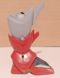
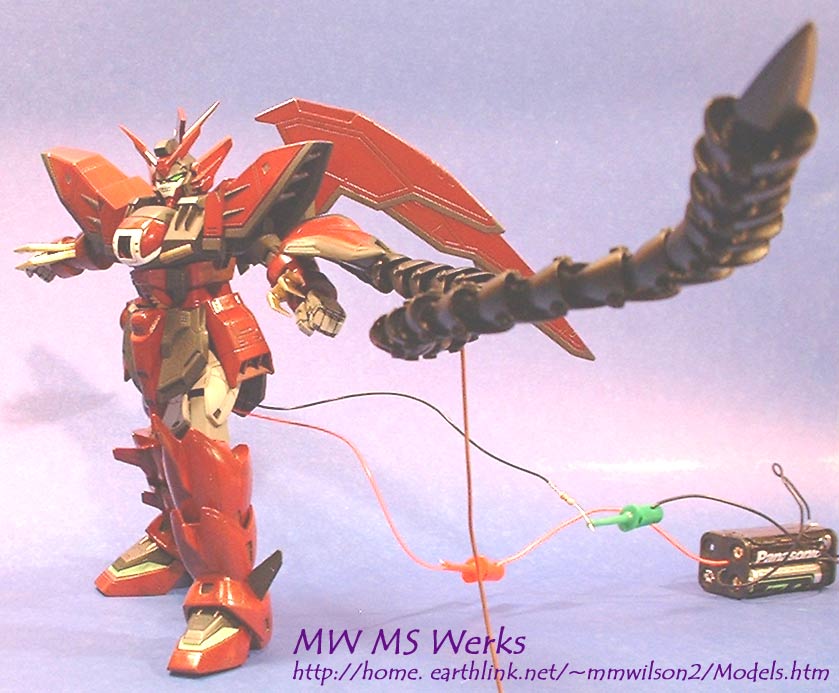
Weapons: Epyon is unique in the Gundam Wing universe by having no long-range weapons. Epyon is armed only with a rather large beam sabre and a heat rod. The beam sabre is connected to Epyon's right hip by a flexible cable. In the kit, there are two translucent green beam sabre blades. One is a normal blade, measuring 3 1/4 in. long and the other is the "most excessive beam sabre" blade, measuring a whopping 5 1/2 in. long. Just for a sense of size, if stood on end this blade would reach up just past Epyon’s chest gem! This is the blade that Zechs uses to slice the Balji space station in half during the White Fang revolt, and the kit version looks it. Both blades are well done, making the beam sabre a real highlight of the kit. The cable that connects to Epyon's hip also gives the modeler a convenient means of lighting the beam sabre blades. Unfortunately, the beam sabre plastic doesn't really glow when lit edge on, so lighting is fairly ineffective.
The heat rod is mounted to Epyon's arm through a rather small shield. In the anime, the entire heat rod can be stored in this small shield, with only the end spike showing. The heat rod, much like Altron's Dragon Fang arms, also could stretch to any length the plot requires. In reality, there is no way in the world all of the links of the heat rod could be stored in the shield; it's a pure bit of anime fantasy.
There are 3
weak links (Get it? Weak
"links"?) to the kit heat rod.
The first is the heat rod links are hooked together by overlapping
plastic hinges and pins. This is almost
certain to wear out and give Epyon a floppy rod. I originally planned on taking an idea from modern MG kits to
prevent heat rod joint wear out -- a wire core. As I assembled the kit heat rod links, each one was drilled out
and threaded along a wire. The second
weak link is the links themselves. They
are too big compared to what they 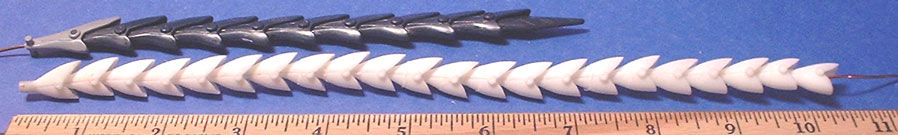 should
be in the anime. Too long, too flared
and overall the wrong shape—the more I made, the less I liked it. Instead of continuing to make a ridiculous
rod, I scratch built a new master for a RTV mold and cast a whole new set of
resin links. PolyTek, whom I highly recommend, supplied
the 71-20 RTV and 1512X resin. With the RTV mold, I could cast as many
links and extend Epyon’s heat rod to be as insanely long as seen in the
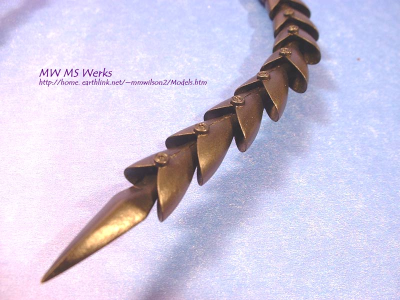
Anime—which brings me to the third weak link—heat rod length. Above is the kit supplied heat rod with the
new resin heat rod links laid out together (the resin links are unfinished and
still have some flash from the molding).
The total kit rod length with spike is 7 ½ inches; the new resin links
would be over a foot long when finished without the spike. As seen above, each heat rod link was
drilled out and a stiff, solid 14 gage wire run through the entire thing. The
detail shot to the left (again, the resin links are straight from the mold and
unfinished) shows the newer links are shorter and fatter individually with one
should
be in the anime. Too long, too flared
and overall the wrong shape—the more I made, the less I liked it. Instead of continuing to make a ridiculous
rod, I scratch built a new master for a RTV mold and cast a whole new set of
resin links. PolyTek, whom I highly recommend, supplied
the 71-20 RTV and 1512X resin. With the RTV mold, I could cast as many
links and extend Epyon’s heat rod to be as insanely long as seen in the
Anime—which brings me to the third weak link—heat rod length. Above is the kit supplied heat rod with the
new resin heat rod links laid out together (the resin links are unfinished and
still have some flash from the molding).
The total kit rod length with spike is 7 ½ inches; the new resin links
would be over a foot long when finished without the spike. As seen above, each heat rod link was
drilled out and a stiff, solid 14 gage wire run through the entire thing. The
detail shot to the left (again, the resin links are straight from the mold and
unfinished) shows the newer links are shorter and fatter individually with one 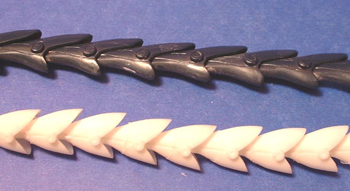 panel
line, and are based on how the anime rod looked most of the time
(episodes 34, 36 & 49 are great reference material). As with all things anime, the rod links
looked different in different scenes or poses and the main attempt was make
something much better than the kit in capturing the general shape of the heat
rod. One key feature retained from the
kit heat rod design is the flexibility; the heat rod should be as posable as a
whip. The picture to the right shows
how flexible the new links are compared to the kit links.
panel
line, and are based on how the anime rod looked most of the time
(episodes 34, 36 & 49 are great reference material). As with all things anime, the rod links
looked different in different scenes or poses and the main attempt was make
something much better than the kit in capturing the general shape of the heat
rod. One key feature retained from the
kit heat rod design is the flexibility; the heat rod should be as posable as a
whip. The picture to the right shows
how flexible the new links are compared to the kit links.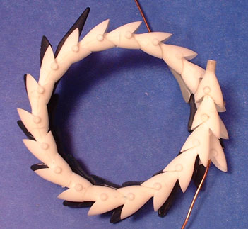 One advantage my links have over the original
is they flex both ways; the kit links can only curl in, as they lock when
straightened out. I still have the molds and some spare links;
if anybody is interested in getting some, e-mail
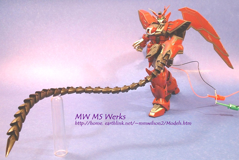
me. In addition to casting newer, more
anime-accurate heat rod links the spike tips were modified. Polyester putty was used to build up the
centerline thickness of the spike while the edges and tip were sharpened. The finished heat rod is shown in my gallery
section. At 25 links and the spike, it
requires a support at full extension to keep Epyon upright!
One advantage my links have over the original
is they flex both ways; the kit links can only curl in, as they lock when
straightened out. I still have the molds and some spare links;
if anybody is interested in getting some, e-mail
me. In addition to casting newer, more
anime-accurate heat rod links the spike tips were modified. Polyester putty was used to build up the
centerline thickness of the spike while the edges and tip were sharpened. The finished heat rod is shown in my gallery
section. At 25 links and the spike, it
requires a support at full extension to keep Epyon upright!
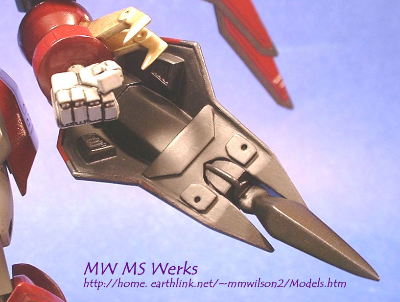
Another failing in this kit is the shield itself. The shield is typical of HG kits, molded on one side only and completely hollow except 2 ugly joints--the heat rod plug and the arm attachment (which would be another plastic-on-plastic joint). Since the shield is such an important part of the heat rod system and therefore a key characteristic of Epyon, and the interior is clearly visible in either mobile armor or regular mode, I decided to take some time and fix it up. First, the attachment point for the shield is a plastic receiver the left forearm plastic peg plugs into. The receiver was cut off, and a spare PC cap put in (trapped with Milliput) to eliminate the plastic-on-plastic joint. I then scratch built an interior using the shield from TallGeese III, which has a fair degree of interior detailing, as a model. Since the shield interior is never clearly seen during Gundam Wing, I had considerable artistic license. The results can be seen to the right; keep in mind the only original interior detail is a rectangular plate used to secure the heat rod PC cap. The joint cover for the heat rod PC cap was made out of 0.02 in. styrene and copper wire. All other details on the inside were scratch built from either plate styrene, Milliput, SGT or cast from resin (the verniers/vents). It sure as heck looks a lot better than it did.
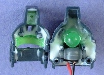 Miscellaneous: Epyon was one kit I decided up front to
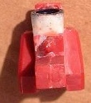
light up. The eyes were relatively
straightforward to light. The clear
green eyepiece was trimmed on the inside to maximize space. A green LED was mounted with super glue and
resin on the back of the head, the wiring run behind the neck PC. Unlike my DSH, Epyon's head can still turn
and pivot, though it is somewhat limited by the wiring. The wiring can be stored in the torso when
not in use, and run down through the leg to an external power supply when I
want it lit. I also considered lighting
up the search-eye gem in the chest, but didn’t. Instead, it was coated with Future Floor Wax to make it
exceptionally glossy. Under even dim
lighting conditions the gem glows anyways, so lighting wasn’t worth the
trouble. One other quick fix to make
painting easier was to snip off the lower torso pegs. With the transformation mechanism, the upper and lower torsos are
held together through a PC connector.
With the pegs snipped off, I can easily separate the upper and lower
torso sections for easy painting and access to the head LED wiring.
Miscellaneous: Epyon was one kit I decided up front to
light up. The eyes were relatively
straightforward to light. The clear
green eyepiece was trimmed on the inside to maximize space. A green LED was mounted with super glue and
resin on the back of the head, the wiring run behind the neck PC. Unlike my DSH, Epyon's head can still turn
and pivot, though it is somewhat limited by the wiring. The wiring can be stored in the torso when
not in use, and run down through the leg to an external power supply when I
want it lit. I also considered lighting
up the search-eye gem in the chest, but didn’t. Instead, it was coated with Future Floor Wax to make it
exceptionally glossy. Under even dim
lighting conditions the gem glows anyways, so lighting wasn’t worth the
trouble. One other quick fix to make
painting easier was to snip off the lower torso pegs. With the transformation mechanism, the upper and lower torsos are
held together through a PC connector.
With the pegs snipped off, I can easily separate the upper and lower
torso sections for easy painting and access to the head LED wiring.
A few more notes on the beam sabre. To make the beam sabre blades glow they were frosted by dipping in and scrubbing with an acetone-soaked cloth. Scrubbing translucent plastic with acetone also eliminates any scarring from sanding or filing the sprue scars by frosting the whole surface. The kit hands were replaced with detailed with B-Club sets. One of the right hands was fixed to fit the beam sabre handle (which comes apart to fit into the handle) since the kit hands tend to be too weak over time to grip heavy weapons. Other hands were made in various poses, so there are several posing options. Like most HG GW kits Epyon has a number of exposed PC joints, the majority were fixed as described above but there still were exposed PC joints on the wing mounts. The wing PC mounts have a lot of room for joint covers, so these were made of sheet styrene strips joined and reinforced with SGT on one side, and Tamiya Polyester Putty on the top and other side. Replacing the kit rear armor skirt hinges eliminated the need for PC covers there.
Painting: One of this kit's best features is it's easy to paint. The question is, what colors to use? I was not trying to match the bare plastic colors; all of it would be painted. For the black, I used Model Master AC interior black. This is a slightly gray tinted black, and it looks great in this scale--not as harsh as a true black. The red/maroon color was trickier. Since Gunze Sangyo lacquers weren’t available to me at the time (They are now! Check it out at Moschini’s Model Shop), I used Floquil Railroad colors. These enamels are compatible with Model Master enamels, and come in a wide variety of unique colors. For Epyon, the best color was Wisconsin Central Maroon (WCM)—yes, that is a train line...
To pre-shade ("Max" technique), WCM was mixed with AC Black in a 5 to 1 ratio, giving a darker, but still reddish tinted base coat. WCM was then applied to the flat areas, leaving the high edges and crevices the darker base coat. Ultimately a very subtle “Max” technique effect was produced, which is what I wanted to produce a fairly Anime accurate but still visually interesting paint job. This was the most time consuming step, requiring fine line painting at some points. All this was set aside to cure before penciling in panel lines. For the lighter gray parts, Decrylon brand primer was used. Dullcoat or glosscoat sealing when using primer as a color coat is a good idea. Primer tends to be soft and almost tacky until fully cured, so dullcoat or glosscoat helps protect it. The gold portions were all airbrushed with MM Bright Brass.
Detail painting is always fun with anime--what color is this part? It depends. I spent a few hours watching episodes 34 to 49 of GW, and pulled numerous screenshots from a couple websites (http://www.epy0n.com/winggallery.htm and http://pictures.gundamw.net/gwscreens.html) to get as much info as possible. Unfortunately, GW mecha are not drawn or colored consistently from frame to frame, let alone throughout the series. There are a few “consistent” points from GW that point out errors from the instructions:
 1. There are "sideburns" molded on
the white face piece (left). These
should be maroon.
1. There are "sideburns" molded on
the white face piece (left). These
should be maroon. 
2. The interior of the shoulder guards has 3 slats. These should be light gray.
3. The green clear foot part--none of it should be painted. Or, the clear green parts should have the last triangle section painted black. It is unfortunately shown both ways in the anime, so take your pick…
4. The knee blocks are darker than the thigh—about gunship gray.
Other observations (seen/not seen at least once):
1. The wrists have a flat circular region around the wrist polycap socket. This circle is sometimes gray like the hands (right), BUT NOT ALWAYS.
2. There is a small gold diamond on the beam sabre hilt (left).
My Epyon Gallery (MS Mode)
Bring it
on, Wing Zero! A Little
Discipline is in Order here… Whip it…Whip
it Good!! Whip Attack Standing,
Back Standing,
Side Face/Chest
Close up Torso,
Eyes Lit Shield
Detail Heat
Rod Detail Knee/Back
Detail
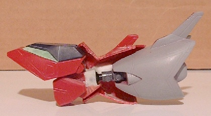
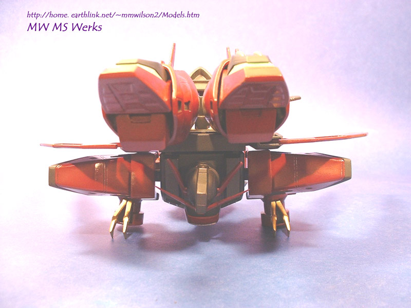
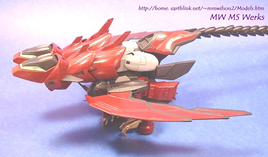
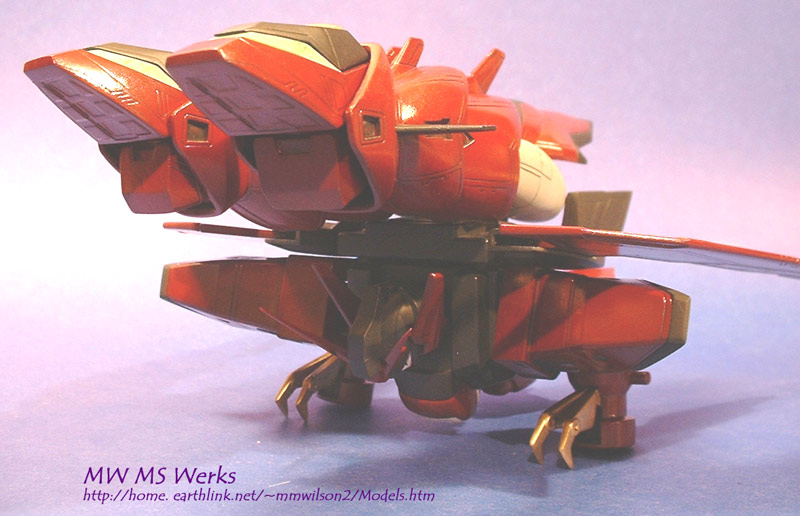
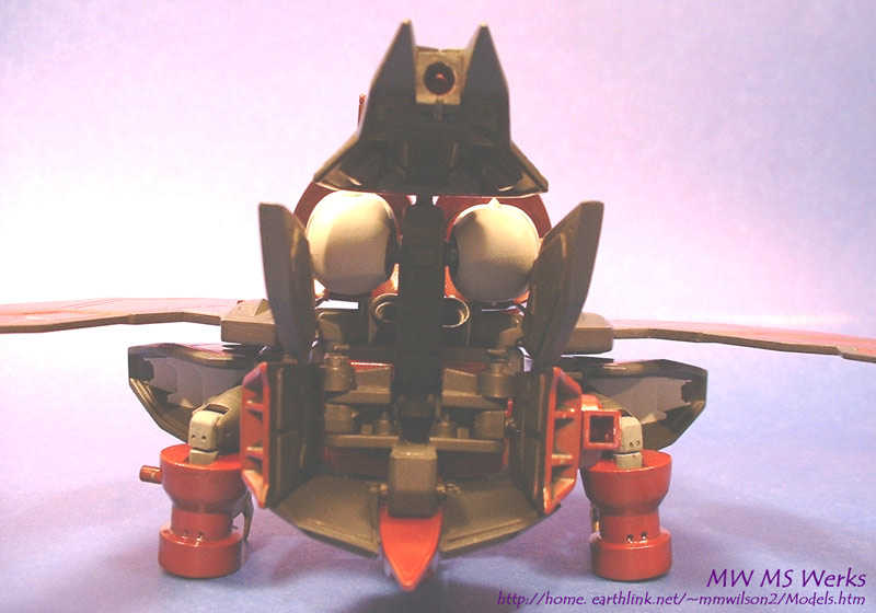
Mobile Armor Shots
Front Front,
Low Top Side Side, Low Hip Detail