Miniature LED Soldering
This is advice for those wanting to use 402 package LEDs—LEDs that are surface
mounted to a circuit board, and measure about 1 mm in width, maybe 2mm in
length.
The following words are from Tetsujin, of http://scope-eye.net/. It was so freakin’ useful, I decided to add pictures to his words. My comments are in red.
First priority: don't lose the damn LED. This is important
and it shapes the whole process of attaching wires to it. Once you get
the first wire on it, this is much easier.
So first thing is to get a handle on that LED so you can work with it and not
have it escape all the time. My usual approach is to grab the front end
of it with pliers, and wrap a rubber band around the grips to hold
tension. Try to get it such that you have clear access to the
terminals. You don't want the pliers to wind up acting as a heat sink, or
else you won't be able to get a good solder joint. So try to grab just
the lens. I
used a set of self closing or spring loaded tweezers, held in a dollar store
“helping hand” base:

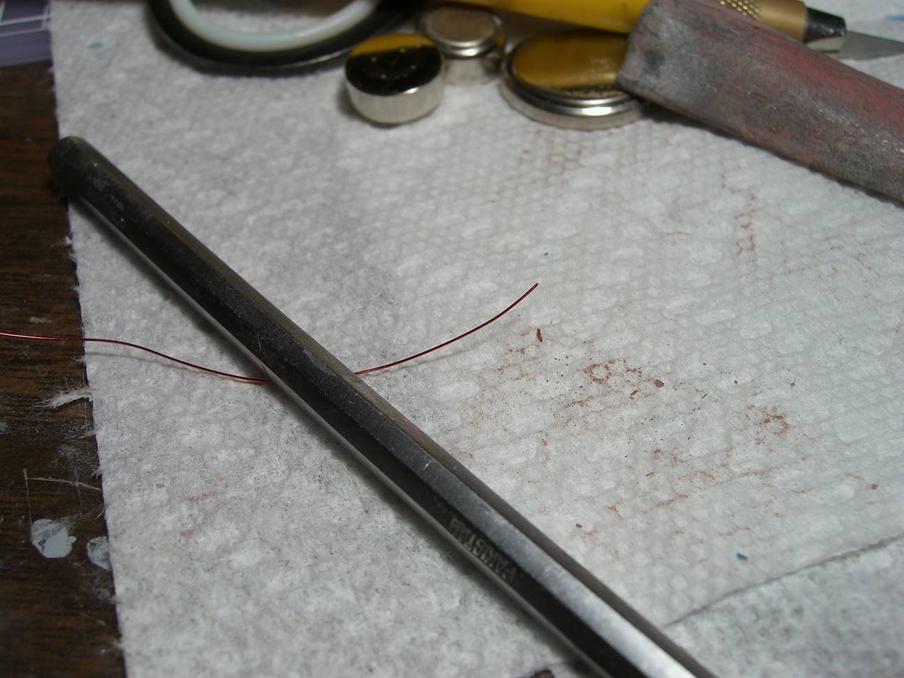
You need some kind of wire: the two kinds I use most are magnet wire and 30 AWG stranded teflon wire. The stranded stuff is great because it's resilient enough to survive even if it's run across moving joints (within reason, of course). The magnet wire is great because it can fit absolutely anywhere. Magnet wire is a bit more frustrating to strip, since the insulation is painted on: I usually sand it off. (There may be a chemical solution that'll do the job...). I used magnet wire, as it was on hand. Below shows how thin the stuff is, before you remove the insulation. It’s maybe twice the thickness of hair.
A third option is wire wrap wire: it's a thin,
solid-conductor wire with a separate rubber insulation layer. It's very
easy to strip and work with, but neither as thin as magnet wire nor as
resilient as stranded wire.
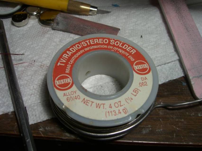
Heat up the iron. Put some solder on it - just enough to wet the
tip. Swipe the
back of the LED with flux—this is a critical step in my experience. Also dip
the bare wire in flux too.
Wipe some of that solder onto each terminal of the LED. It
should form a smooth coating on the terminal, possibly with a little curvature (the following is impossible to
film while doing by yourself, so use theatre of the mind here). Now apply some solder
to the wire: if you're using stranded, you should strip probably about 4-5mm
and twist the end, then apply heat and fresh solder to the wire. The
solder should flow onto the wire, coating it but without bulking it up too
much. The tip
of the wire should go from looking copper to silver—not bulky, just a thin coat.
This is where the flux has paid off. Once the end of the wire is soldered, trim the soldered
end, leaving just enough to connect to your LED terminal. (Soldering the
stranded wire before trimming it gives you a better end, generally.) If
you're using single-strand wire, strip the wire then trim it, and then apply flux and solder. You probably
won't get as smooth a coating on a solid wire, but just get some on there.
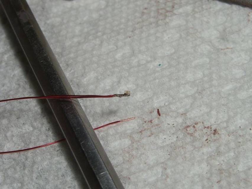
Now you're ready to connect the first wire to the LED. Using a vise
or something hold the pliers upright so you have access to the LED and both
hands free. Wet the soldering iron with a little bit of solder
again. Bring the wire in contact with the terminal; apply heat and the
fresh solder from the iron's tip. Let the solder on the wire and terminal
melt, then while holding everything in position remove the heat. The
solder joint should be smooth (no "puckering" inward around the wire,
just a smooth little blob with a wire sticking out). Repeat for the
second wire. This
should not involve a long touch—just enough soldering iron contact to get the
solder to flow.
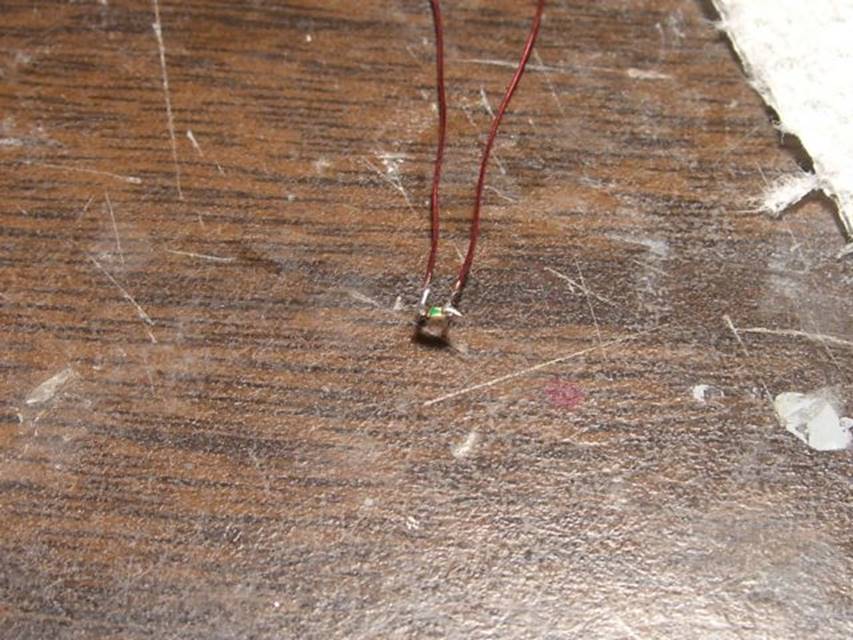
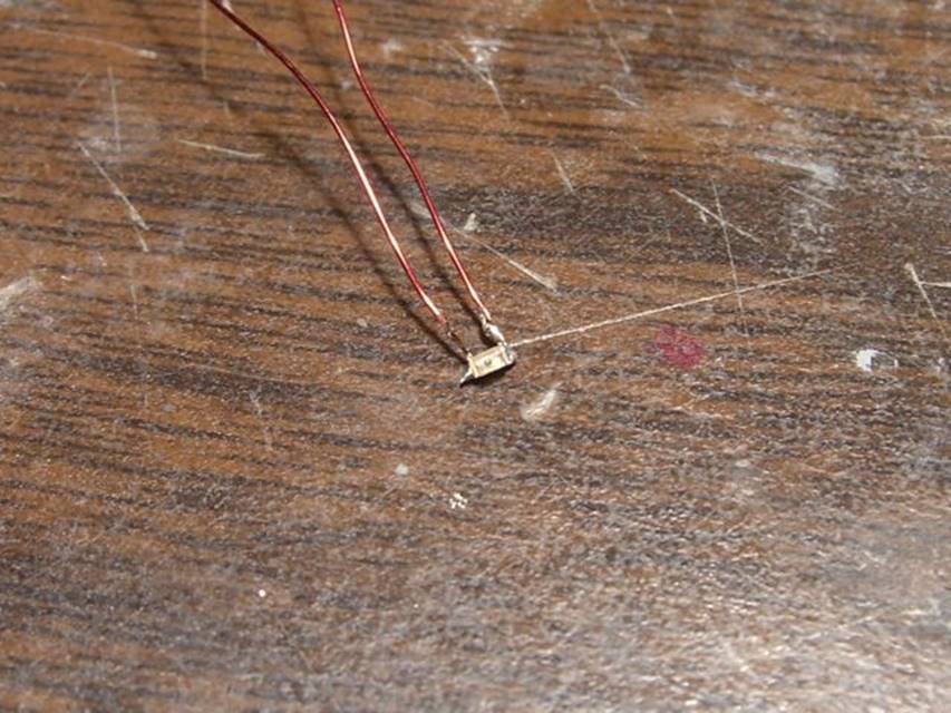
After the first wire is on the whole deal is a lot easier to handle - and
if you did drop the LED at this point, it would still be about a million times
easier to find than it was without a wire attached.
Thanks again to Testujin for the advice. It worked just fine, as the pics above show. I did not use any special tip on the soldering iron, I just made sure it was clean. Keep in mind these soldering joints are extremely fragile (that’s Italian, you know). Use only in places where you need itty bitty, and can protect the solder join.
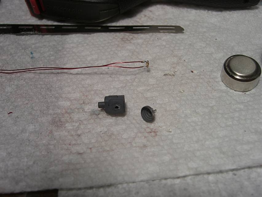
I did a small test with the Zaku II 2.0 monoeye lens--keep in mind the monoeye lens is about 4 mm in outer diameter, and the 402 LED fits behind it very well. Below shows the option part (4mm across), the kit piece the mono eye attached too, and the completed SMD LED assembly. Itty bitty.
I roughed up the outer surface of the lens with 400 grit sandpaper and stuck the itty bitty LED behind it. I did need to carve some shallow channels to run the wire out of the mooneye lens, but those are both minor operations. Gives a nice evil monoeye look!
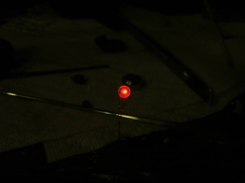
If I didn’t sand the lens, the rectangular nature of the LED would show. With the light sanding, the lens became a diffuser as seen above, evenly distributing the light. The lens isn’t quite as bright in the picture, but it is more than bright enough for monoeye purposes. In the image below, the monoeye was drilled out a bit to allow the SMT LED to fit inside better, with a dab of clear silicone to act as glue and a diffuser, giving a slightly different look.
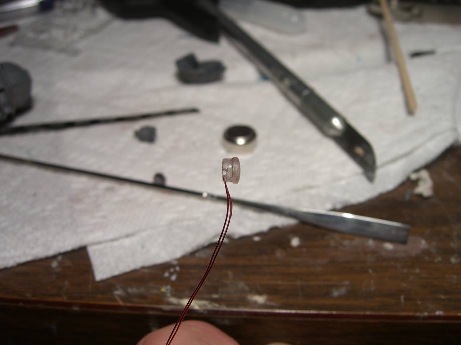
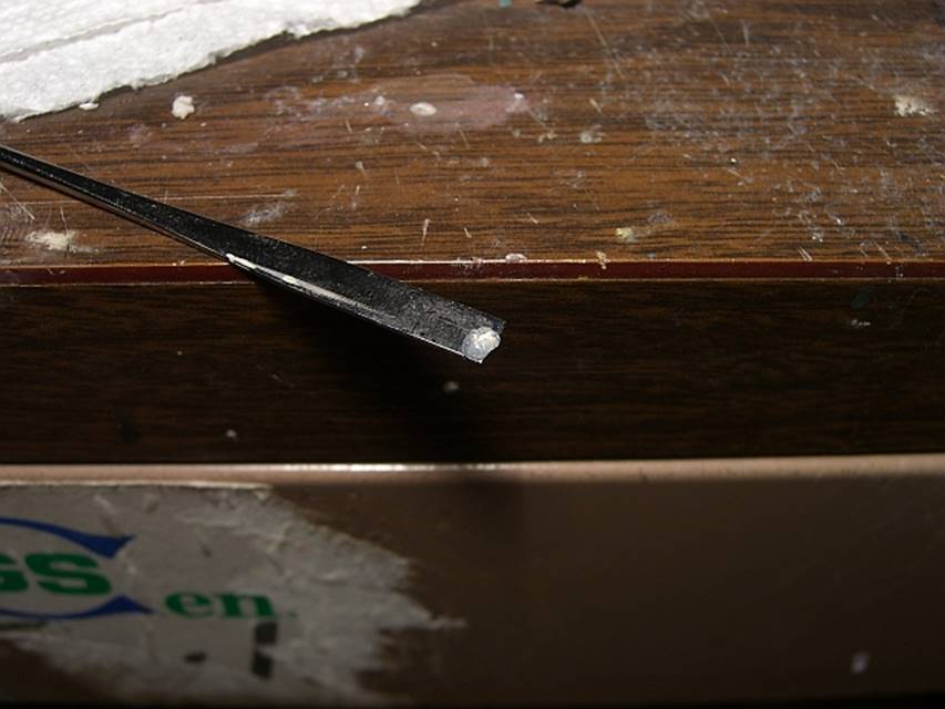
The Silicone caulk worked out really well here. It is a little on the messy side to deal with, but acts as a perfect glue/flexible insulation. I uses the standard GE silicone from the hardware store. And don’t let “clear” fool you, it is fairly cloudy when dry and works wonderfully as a diffuser.
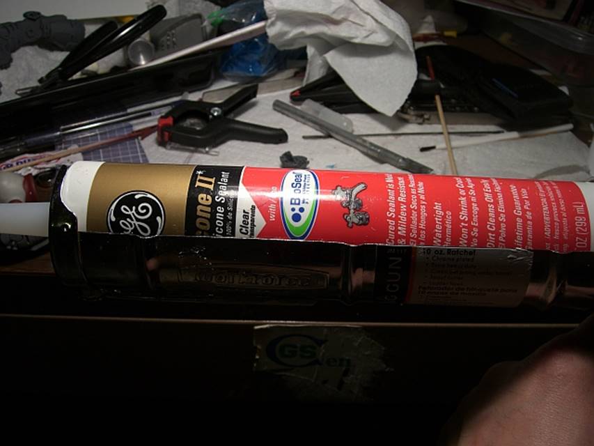
Al ittle dab will do—note it isn’t realy clear.
Hope this helps. Working with SMT LEDs is kind of intimidating until you try it, but once you get it, it isn’t that big a deal. A word of advice—buy at least twice what you think you need— they are cheap, and you WILL lose them.